
Summary of Contents for Rinex GA8500
- Page 1 GuideTRAX User Manual Addendum Software Version: Part Number: 1-1293 Revision: Issue Date: March 2008...
- Page 2 By use of this system you agree that RINEX is not liable or responsible for any damage whatsoever to the vehicle, any property, personal...
- Page 3 GuideTRAX User Manual Addendum Written for GuideTRAX Version 3.3 Publication Date, March 2008 © Copyright 2008 by RINEX Technology. All rights reserved. Acknowledgements ® Windows XP is registered to Microsoft Corp. Other products and trademarks mentioned in this manual are the property of their registered owners.
- Page 4 Product or, at RINEX’S option, the cost of replacing the defective item. In no event will RINEX be liable for any loss of production, loss of profits, loss of use for any special, indirect, incidental, consequential or contingent damages, even if RINEX has been advised of the possibility of such damages.
- Page 5 The end purchaser is solely responsible for the cost of transportation of the Product to RINEX or an authorised RINEX dealer and the Product is at the end purchaser's risk whilst in transit. For any questions regarding warranty service or to obtain information regarding the location of any of RINEX’s approved dealers, contact RINEX at the following address:...
-
Page 7: Table Of Contents
The GA8500 Components ............14 Top Panel Buttons ..............15 The AS300 Hub ................. 16 The GA8500 Power Management System ......... 17 2.4.1 The GA8500 Power Control Switch ..........17 2.4.2 ... -
Page 9: Introduction
Introduction... - Page 11 This manual is designed as an addendum to the GuideTRAX user manual supplied with the GA8500. It should be read in conjunction with the supplied GuideTRAX user manual and the subtle differences between the products will be described in this manual.
-
Page 12: This Manual
This manual is designed for use of the GuideTRAX software operating on the GA8500 guidance system (hardware). The RINEX Saturn H series hardware has now been superseded by the GA8500 as has GuideTRAX V3.2 with the updated software, GuideTRAX V3.3. -
Page 13: The Ga8500
Furthermore the GA8500 incorporates the latest in low power management design which enables the system to operate without cooling fans or large heat sinks. In addition to this the GA8500 has an intelligent power system which can sense ignition status and abnormal input power to protect the computer from fluctuations in vehicle power supply systems. -
Page 14: Guidetrax V3
GuideTRAX V3.3 has been designed specifically to operate on the GA8500, however it retained the same “look and feel” as the previous version. This allows existing users to start working as quickly as possible with the new products. -
Page 15: User Manual Amendments
GA8500. Wherever the HL, HT or HR manual makes reference to Saturn H series, it should now be in reference to the GA8500 product. Furthermore wherever the manual references to HL, HT or HR model, this should reference the GA8500 standard model plus any applicable optional items. -
Page 16: Guidetrax V3.2 Ht User Manual
Section 8.2.5 The GA8500 does not PCAN view software and the HBOX test has been upgrade to System Test. Section 8.2.5.1 The GA8500 does not use the Datalux or RNX screen controllers. Appendix 2 The GA8500 specifications are supplied in Appendix 1 of this Addendum. -
Page 17: Guidetrax V3.2 Hr User Manual
Section 9 The GA8500 does not support the Beeline Arro product. Section 10.2.1 The GA8500 utilises the USB port on the left hand side of the screen for connection of the FieldNET radios. Section 11.1 The section on opening the Launcher is obsolete and the user is should Section 3.4.1. - Page 18 Section 11.2.1 The GA8500 utilises the USB port on the left hand side of the screen for connection of the FieldNET radios. Section 12.1 The section on opening the Launcher is obsolete and the user is should Section 3.4.1. Section 12.2.4 The GA8500 does not support either the original JD StarFire™...
-
Page 19: The Ga8500
The GA8500... - Page 21 The new GA8500 is based on a full colour 22cm touch screen from RINEX. The screen is daylight viewable and touch sensitive which provides a fully graphical user interface which is easy to operate in a moving vehicle. To operate any function on the system it is a simple case of touching the screen on the appropriate button.
-
Page 22: The Ga8500 Components
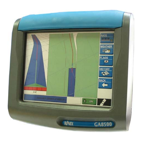
Figure 2-1 The GA8500 and AS300 The GA8500 system specifications are shown in Appendix1. The GA8500 features a row of buttons along the top panel of the console, which are described in Section Top Panel Buttons2.2. A USB port is located on the left hand side of the touch screen. The USB port is used for transfer of data and uploading of new software. -
Page 23: Top Panel Buttons
2.2 Top Panel Buttons The GA8500 features a row of buttons along the top of the console. There is a total of seven buttons of which three are preconfigured for specific operations. The power control button enables the unit to be switched On and Off under normal operating conditions. -
Page 24: The As300 Hub
2.3 The AS300 Hub The AS300 Hub is used for connecting all peripheral components to the GA8500 system. The AS300 Hub is also used to supply DC power to the GA8500 console. The AS300 Hub is shown in Figure 2-4. -
Page 25: The Ga8500 Power Management System
Section 3.4 for further details. If Launcher mode is accidentally started, select the top option “Start GuideTRAX” to return to normal operation. To turn the GA8500 Off, press and hold the top panel power button until one beep is heard. The system will display a shutdown progress screen while it is saving data and settings. - Page 26 GA8500 can be used without any other switches being required. The GA8500 must be installed with the optional power cable which contains an ignition sense wire. The system will start up and shut down with the vehicle, when the ignition key is turned. No further user intervention is required.
-
Page 27: Guidetrax V3.3
GuideTRAX V3.3... - Page 29 GuideTRAX V3.3 is the latest software from RINEX and is designed specifically to operate with the GA8500. It incorporates all major features of previous GuideTRAX software versions where RINEX has earned its reputation as the easiest software to operate. Specifically GuideTRAX V3.3 utilises the functionality of the GA8500 features to continue this...
-
Page 30: The Start Up Screens
3.1 The Start Up Screens As the GA8500 is being powered up several screens will appear as it goes through the start up phase, the GuideTRAX V3 will be displayed as shown in Figure 3-1 confirming operation of the GA8500. Once the system is completely operational the main guidance screen will be displayed as shown in Figure 3-2. -
Page 31: Setting The Remote Master Switch
GuideTRAX V3 can be configured in several formats for individual user requirements. This action is often referred to as the Master Switch, or if remotely connected to the GA8500, as the Remote Master Switch. GuideTRAX V3 is compatible with numerous flow controllers and can detect when the flow controller Master Switch has been toggled. - Page 32 Sense Dipole (dipole) on flow AutoSPRAY port controller with AutoSPRAY Master Switch on Connect relevant RINEX data cable to Port Flow Control flow controller A. Flow controller (serial interface (serial protocol) protocol) must be compatible with RINEX systems, set correct Flow Controller in...
- Page 33 This example sets the Remote Master Switch for a 12Vdc switch on Control Port C. The instructions for installation of a toggle switch and connecting it to the AS300 Hub can be found in the GA8500 Installation Manual. SETUP-VEHICLE SETUP SWITCH SETUP...
- Page 34 Remote Master – 12V dc dipole To use dipole switch connected to the AutoSPRAY connector as shown in Table 3-1 follow the steps below. The steps commence from the main screen as shown in Figure 3-2. This example sets the Remote Master Switch for a 12Vdc dipole switch on the AutoSPRAY connector.
-
Page 35: Setting The Remote Buttons
3.3 Setting the Remote Buttons The GA8500 has four user configurable buttons which can be used as “Hot” keys or buttons for selected functions. The buttons, 1 to 4, are shown in Figure 2-3. The buttons can be programmed using the Remote Buttons function of the GuideTRAX V3 software. -
Page 36: The Launcher
Off position, then hold the Power Control button, shown in Figure 2-2, for approximately two seconds until two short beeps are heard. Releasing the Power Control button will then cause the GA8500 to start into the Launcher program. The main screen of the Launcher program is shown in Figure 3-6. -
Page 37: Appendix
Appendix... - Page 39 APPENDIX 1 GA8500 GUIDANCE SYSTEM GA8500 console Physical Size 230 (w) x 215 (h) x 70 (d) mm Weight 1920grams Cable 200mm Environmental Operating Temperature 0°c to +50°c Storage temperature -10°c to 60°c Display Graphical / daylight viewable 450Nit Size...
Need help?
Do you have a question about the GA8500 and is the answer not in the manual?
Questions and answers