
Summary of Contents for Aloxy Pulse v01
- Page 1 Aloxy Pulse v01 Instruction manual EN I_505_Aloxy Pulse Instruction Manual EN...
- Page 2 Instruction manual for the Aloxy Pulse v01 Language: English Document identification: I_505_Aloxy Pulse Instruction Manual EN Document name: I_505_Aloxy Pulse Operators Manual EN Last revision: Jul 28, 2020 Manufacturer: © Aloxy NV Sint-Pietersvliet 7 2000 Antwerp Belgium TEL: +32 472 18 33 31 info@aloxy.io...
-
Page 3: Table Of Contents
SE IN AREAS SUBJECT TO EXPLOSION HAZARD 5 INSTALLATION AND COMMISSIONING 5.1 D IMENSIONS 5.2 I NSTALLING MOUNTING 6 USAGE OF THE ALOXY PULSE 6.1 M OUNTING THE LOXY ULSE TO AN INDUSTRIAL ASSET 7 INSPECTIONS AND MAINTENANCE 7.1 B ASIC SAFETY INSTRUCTIONS 7.2 C... - Page 4 9 TECHNICAL DATA I_505_Aloxy Pulse Instruction Manual EN...
-
Page 5: Legal Information
Before installing, configurating or operating the Aloxy Pulse or performing any maintenance activities associated with it, read these instructions carefully! 1 Legal information Warning notice system This manual contains notices you have to observe in order to ensure your personal safety, as well as to prevent damage to property. -
Page 6: Introduction
This instruction manual includes specifications, installation, basic setup and configuration, and maintenance and troubleshooting information for the ALOXY Pulse. Do not install, operate, or maintain a ALOXY Pulse without being fully trained and qualified in valve, , and accessory installation, operation, and maintenance. To avoid personal injury or property damage, it is important to carefully read, understand, and follow all of the contents of this manual, including all safety cautions and warnings. -
Page 7: Checking The Consignment
For instance, by attaching the Aloxy Pulse to the hand wheel or lever of a manual valve, it can monitor the position (open or closed) of the valve in real-time. By attaching the Aloxy Pulse to rotating equipment such as a motor or ventilation unit, it can monitor vibrations or ambient temperature and in real-time send an alert when a certain threshold is exceeded. -
Page 8: Marking Label
This product is an FCC approved device. Changes or modifications to the ALOXY Pulse that are not expressly approved by the party responsible for compliance may void your authority to operate the device. 3.1 Marking label The identification label of the Aloxy Pulse is attached to the bottom of the device: Name plate dimensions 67,2 mm (L) x 15.6mm (W) - Page 9 1. Manufacturer 7. ATEX/IECEx marking for hazardous area 2. Manufacturing QR code 8. Serial number (Order code) 3. Warning 9. Product name, type and year of 4. Protection class manufacturing 5. ATEX / IECEx marking for hazardous area 10. Approvals 6.
-
Page 10: Security Information
The content reflects the technical status at the time of publishing. ALOXY reserves the right to make technical changes in the course of further development. -
Page 11: Warning Symbols On The Device
4.2 Warning symbols on the device Consult operating instructions 4.3 Laws and directives Observe the test certification, provisions and laws applicable in your country during connection, assembly and operation. These include, for example: National Electrical Code (NEC - NFPA 70) (USA) ... -
Page 12: Installation And Commissioning
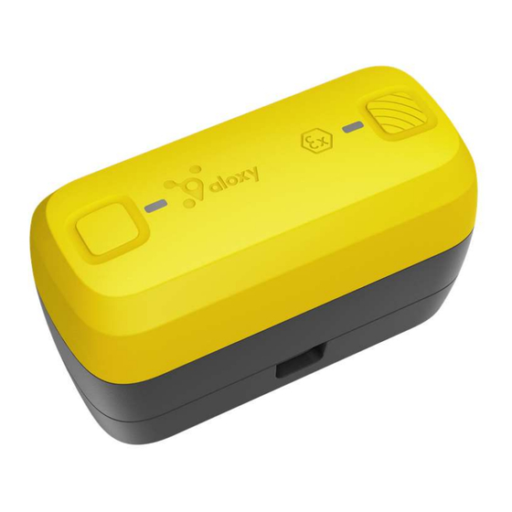
Install the equipment as per the NEC NFPA 70 1. Aloxy logo, Ex marking & NFC area: The Aloxy logo indicates the area of the Aloxy Pulse device that can be scanned by an NFC reader or NFC-enabled smartphone or tablet. -
Page 13: Dimensions
In order to ensure the degree of protection of the housing (IP69), protect the housing from mechanical impact energy: ALOXY Pulse not greater than 2 Joule 5.1 Dimensions The Aloxy Pulse has the following dimensions: length 88.5mm x with 41.2mm x height 50.3mm, including the mounting bracket. I_505_Aloxy Pulse Instruction Manual EN... -
Page 14: Installing / Mounting
60mm: 5.2 Installing / mounting WARNING Before mounting the ALOXY Pulse: Always wear protective clothing, gloves, and eyewear when performing any installation procedures to avoid personal injury or property damage. Check with your process or safety engineer for any additional measures that must be taken to protect against process media. -
Page 15: Usage Of The Aloxy Pulse
WARNING Loss of explosion protection The Aloxy Pulse can only be used within a process temperature range of -40°C ≤ Ta ≤ +70°C when mounted on pipes or machines. CAUTION Loss of type of protection Damage to device if the enclosure is open or not properly closed. The type of protection specified on the nameplate or in technical data is no longer guaranteed. - Page 16 When the Aloxy Pulse should measure a certain motion, for instance the motion of the hand wheel of a manual valve to monitor the valve’s position, make sure that the Aloxy Pulse device is attached to the moving part and follows the same motion as the part it is monitoring. No other...
- Page 17 A. Installation using double straps (metal or plastic) on a tube- or bar-shape surface: This method ensures good, non-intrusive fixation of the Aloxy Pulse to an asset suitable for instance for movement detection and vibration monitoring. Typical applications are manual valve position monitoring by attachment to a valve lever or a spoke of the valve wheel, vibration monitoring of a tube, asset tracking, etc.
- Page 18 Torque on screws regarding plastic mounting bracket. The maximum torque of the mounting plate must not be exceeded 1 Nm (0.73 ft lb). This method ensures good, non-intrusive fixation of the Aloxy Pulse to an asset suitable for instance for movement detection and vibration monitoring. Typical applications are manual valve position monitoring by attachment to a valve lever or a spoke or outer ring of the valve wheel, vibration monitoring of a tube, etc.
- Page 19 Use M5 bolts or screws with a maximum head height of 4 mm, such as hexagon socket head (DIN 7984) cap screws with low head. This method ensures excellent, but intrusive fixation of the Aloxy Pulse to an asset suitable for instance for movement detection and vibration monitoring. Typical applications are manual valve...
- Page 20 14 kg (ca. 137 N) E. Installation on a surface using double sided foam sticker: This method ensures fair, non-intrusive fixation of the Aloxy Pulse to a flat asset surface suitable for instance for movement detection and temperature monitoring. Typical applications are asset tracking, temperature monitoring around a motor, etc.
- Page 21 Aloxy Pulse device align within the mounting bracket (a). Slide the Aloxy Pulse device to the right-side until it locks in position (b). Check that the edges of the Aloxy Pulse device perfectly align with the edges of the mounting bracket.
-
Page 22: Inspections And Maintenance
7.1 Basic safety instructions DANGER The ALOXY Pulse contains one primary lithium metal battery pack. Under normal conditions of use, the battery materials are self-contained and are not reactive as long as the batteries and power module integrity are maintained. Care should be taken to prevent mechanical, electrical, or thermal damage. -
Page 23: Cleaning The Enclosure
WARNING Do not open the Aloxy Pulse in the field or within an hazardous (classified) area to replace the battery. The device can only be opened in a workshop equipped to handle electronic components. - Page 24 CAUTION Risk of damaging the electronics When opening the Aloxy Pulse, avoid touching the electronic circuits and the green PCB (Printed Circuit Board) to avoid damage. Always ensure you are discharged of static electricity by wearing for instance an antistatic wrist strap band.
-
Page 25: To Insure Ingress Protection Ip69
PCB, to ensure correct operation of the Aloxy Pulse device. Position the new battery on the support in the top shell and close the Aloxy Pulse again by repositioning the bottom shell on top. Close the device by the 4 original screws, using a calibrated torque screwdriver (with Torx T10 head) according to the table 7.4 To insure ingress protection IP69... -
Page 26: Disposal
Refer to the section "Technical specifications for the torque value. Do not exceed torque on screws regarding gasket The Aloxy Pulse is ready for operational use and can be positioned in its mounting bracket as explained in the previous chapter (step 3). - Page 27 9 Technical data Battery powerd wireless IoT sensor, Type ALOXY Pulse vXX Certifications Reference CE conformety The applicable directives and applied standards with their revision levels can be found in the EU ALOXY_D_400_Declaratio declaration of conformity on the Internet. n of Conformity ALOXY This product complies with the following directives: Pulse v01.docx...
- Page 28 LoRaWAN Labo De Nayer PCC-RAD-4918_ed2 PCC-RAD-5034_ed2 Certification ongoing Canada Certification ongoing DASH7 Self-certification based on D7A v1.2 towards reference stack implementation Certification ongoing Canada Certification ongoing Compliant Reference WEEE 2011/65/EU RoHAS 2012/19/EU Enclosure Reference Mounting Horizontal or vertical position Demensions L x H x W 88,5 x 50,3 x 41,2 mm Weight...
- Page 29 Gasket Top shell - bottom shell Is part of the soft part Mechanical Droptest at +20°C A drop from 2 meters and this 5 times on each side. ALOXY strenght at +80°C at - 45°C Impact test at +20°C Resistant to 2 joule ALOXY at +80°C...
- Page 30 Ingress IP65 Water jets. Water projected by a nozzle (6.3 mm) ALOXY Protection against enclosure from any direction shall have no harmful effects. Test duration: 1 minute per square meter for at least 3 minutes Water volume: 12.5...
- Page 31 UV light (material tends to become yellowish with reduced “shining”), however, this effect is only minimal as the Aloxy material is already yellow. The material came from a bright colour to a more fade tone on the Greyscale of 2.5.
- Page 32 4 to 5 years SF12 1 to 3 years Optimal battery -20°C to +50°C ALOXY temperature range Reference Sensors Accelerometer ±2g/±4g/±8g/±16g acceleration scales ALOXY Gyroscoop full-scale angular rate range of ±125/±250/±500/±1000/±2000 DPS Magnetometer dynamic range of ±50 gauss Atmospheric pressure...
- Page 33 Communication LoRaWAN 500m SF and distance to the range 1 km gateways has a profond inpact on the SF12 <2 km battery life. Frequency DASH7 - EU 863-870MHz LoRaWAN - EU 867-870 MHz DASH7 - USA 902-928MHz LoRaWAN - USA 902-928MHz Payload DASH7...
- Page 34 It is an integral part of the described equipment and must be available at all times. Trademarks All names identified by ® are registered trademarks of ALOXY NV. The remaining trademarks in this publication may be trademarks whose use by third parties for their own purposes could violate the rights of the owner.
Need help?
Do you have a question about the Pulse v01 and is the answer not in the manual?
Questions and answers