Table of Contents

Summary of Contents for ifi JOLLY Series
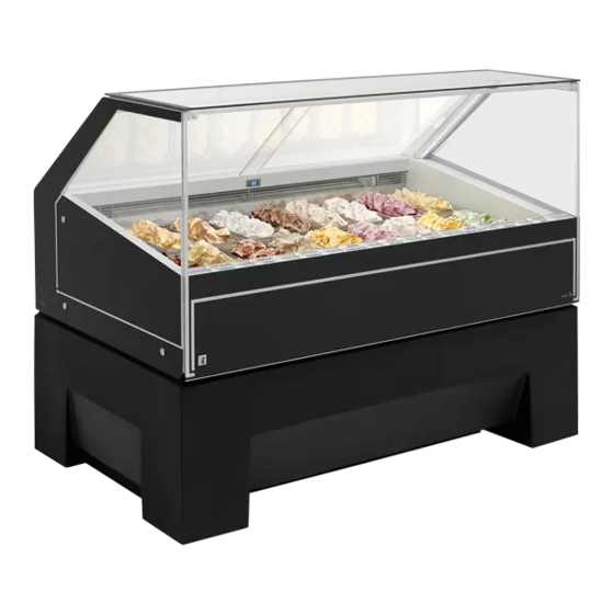
- Page 1 JOLLY Window display case G c C g J g M jC c C c G g C j C g G g C g J c C j Mc C c C c M c J c G g C g J c G j C c J c G j Jc C c G Use and Maintenance Manual 621020794 Instructions translated from the original language...
-
Page 3: Table Of Contents
CONTENTS GENERAL INFORMATION ...............3 DECLARATION OF CONFORMITY (FACSIMILE) ..........3 INTRODUCTION...................... 5 GENERAL HEALTH AND SAFETY STANDARDS ..........5 SYMBOLS ........................ 6 TYPES OF PROFESSIONALS IN CHARGE OF USING THE EQUIPMENT ..6 ATTACHED MANUALS.................... 7 INTENDED USE....................... 7 TECHNICAL SPECIFICATIONS ............8 DISPLAY CASE DESCRIPTION................ - Page 4 START-UP ......................25 AUTOMATIC DEFROSTING.................. 26 HYBRID FUNCTION ....................26 CLEANING FUNCTION ..................26 OPTION BT-TN ...................... 27 SWITCHING ICE CREAM DISPLAY - PATISSERIE DISPLAY ......27 REMOVAL OF THE RUNNERS................28 CLEANING AND HYGIENE ................... 29 MAINTENANCE ................31 CLEANING THE CONDENSER................32 CLEANING THE CONDENSATION EVAPORATION PAN ........
-
Page 5: General Information
01061630412 / Identificación fiscal: Partita I.V.A. / V.A.T. number / Code T.V.A. / 01061630412 Mehrwertsteuernummer / Partida I.V.A.: www.ifi.it / info@ifi.it Internet site / E-mail: Phone / Fax: +39 0721 20021 / +39 0721 201773 / + + 3 3 9 9 0 0 7 7 2 2 1 1 20 0 1 1 7 7 7 7 3 3 (I) Dichiariamo sotto la nostra responsabilità... - Page 6 GENERAL INFORMATION (I) Ai sensi della direttiva Compatibilità Elettromagnetica, sono state applicate le seguenti norme armonizzate: (GB) According to the EMC directive the following harmonized standards have been applied: (F) selon la directive sur la comptabilité électro-magnétique, les normes d’harmonisation suivantes sont appliquées (D) Nach der elektromagnetischen Verträglichkeit Richtlinie wurden die folgenden harmonisierten Normen angewendet: (ESP) De conformidad a las directivas de compatibilidad electromagnética, han estado aplicadas las siguientes normas armonizadas:...
-
Page 7: Introduction
GENERAL INFORMATION INTRODUCTION Dear client, each IFI product is the result of a history of innovation which began in 1962, in which technological knowledge, design, food science and industrial culture were melded together. Traits which translate into project values such as improve- ment to the preservation and the display of foodstuffs, functionality and hygiene, all with particular attention to the wellbeing of people and the environment. -
Page 8: Symbols
GENERAL INFORMATION SYMBOLS IMPORTANT! Extremely important technical information that must not be ignored. CAUTION! All proper measures must be taken so as not to jeopardise the health and safety of people and cause economic damage. DANGER! Extreme hazard situations that may seriously compromise the health and safety of people when ignored. -
Page 9: Attached Manuals
GENERAL INFORMATION Expert technician in refrigeration systems: A technician with proved expe- rience in installation and maintenance operations of refrigeration systems. Proved experience means having attended specific training courses focused on the installa- tion and maintenance of refrigeration systems. He/she must have the information needed for using the equipment. -
Page 10: Technical Specifications
TECHNICAL SPECIFICATIONS TECHNICAL SPECIFICATIONS DISPLAY CASE DESCRIPTION The JOLLY display cabinet has been designed and built for the display and preser- vation of foodstuffs. Main components A – Supporting structure: made up of a moulded polyethylene body. Allows for sup- porting all the components making up the display cabinet. - Page 11 TECHNICAL SPECIFICATIONS...
-
Page 12: Machine And Manufacturer Id Plate
MACHINE AND MANUFACTURER ID PLATE The identification plate shown in the figure is directly applied to the machine. It con- tains the references and all indications needed for safe operation. S.p.A. TAVULLIA (Pesaro) www.ifi.it CLIMATE CL. V/Ph/Hz MADE IN ITALY CURRENT DEFROST dir.2006/42... -
Page 13: Mode For Requesting Technical Assistance
TECHNICAL SPECIFICATIONS A – Manufacturer B – Machine serial number C – Machine Model D – Year of Manufacture E – Climate class F – Mains voltage, phase and frequency G – Rated current H – Current in the defrosting phase I –... -
Page 14: Technical Data
TECHNICAL SPECIFICATIONS TECHNICAL DATA Jolly Jolly Jolly Jolly Jolly Jolly Units of Description measurement 1179 1179 1679 1679 2179 2179 1179 1179 1679 1679 2179 2179 1350 1200 1350 1200 1350 1200 1200 1200 1720 1720 Weight Maximum load on the shelves, and upper level Minimum air expulsion surface. -
Page 15: Perimeter Areas
TECHNICAL SPECIFICATIONS PERIMETER AREAS The figure shows the minimum spaces required for the operator, the customer and the maintenance technician. 1000 Keys: A – Authorised operator area B – Customer service area C – Perimeter Area D – Aeration area of the refrigerated unit During maintenance interventions, the minimum distance must be 700 mm. -
Page 16: Safety Information
SAFETY INFORMATION SAFETY INFORMATION During the design and manufacturing process, the manufacturer has focused spe- cifically on aspects that may cause risks to the health and safety of people interact- ing with the equipment. Caution is anyway extremely important. Safety is also entrusted to all the operators interacting with the equipment. -
Page 17: Handling And Installation
HANDLING AND INSTALLATION HANDLING AND INSTALLATION FOREWORD Handle and install the equipment observing the information provided by the manu- facturer, directly reported on the packaging, the display case and the Owner’s man- ual. As appropriate, anyone authorised to perform such operations shall define a “safety plan”... -
Page 18: Transport
HANDLING AND INSTALLATION TRANSPORT Transportation, also depend- ing on the place of destina- tion, may be carried out by using different means. For an improved stability of the display case in the vari- ous transport phases, two wooden slats (A) are secured to the base frame. -
Page 19: Lifting And Handling
HANDLING AND INSTALLATION LIFTING AND HANDLING The display case is lifted from the means of transport by means of a lift truck. DANGER! The lift forks must be at least 1m long. For a proper and safe lifting, place the forks in line with the centre of bal- ance of the display case. -
Page 20: Positioning The Equipment
HANDLING AND INSTALLATION POSITIONING THE EQUIPMENT IMPORTANT! The manufacturer shall not be held liable for any malfunctioning resulting from failure to observe the following installation instructions. The installation area must be in proper environmental conditions: - Dry and not dusty. - Properly ventilated but not subject to hot and cold air currents. -
Page 21: Removal Of The Transportation Slats
HANDLING AND INSTALLATION REMOVAL OF THE TRANSPORTATION SLATS DANGER! Risk of crushing! The operation must be performed by 2/3 people. - Slightly tilt the equipment as shown in the figure, being careful not to over- turn it, and secure it by using the suitably sized safety mounts (A). -
Page 22: Moving The Display Cabinet
HANDLING AND INSTALLATION MOVING THE DISPLAY CABINET - If connected to the electric- ity supply, turn the display cabinet off and disconnect from the electricity mains. - Screw the support feet (D) positioned on the operator side, to lift them from the ground. -
Page 23: Electrical Connection
HANDLING AND INSTALLATION ELECTRICAL CONNECTION DANGER! Connections to the electric system must be made by specialised and au- thorised staff in compliance with applicable law in the country of use. - Connect the power cable (A) to the mains. DANGER! The power cable must be placed in a protect- ed position under the... -
Page 24: Use And Operation
USE AND OPERATION USE AND OPERATION DESCRIPTION OF THE CONTROLS Control Description Function Switching on / off the equipment Switching on / off the light The instrument is suitably adjusted by the Menu manufacturer and must not be tampered with. Set Point To access the Set Point programming To display the parameters and increase their... - Page 25 USE AND OPERATION Mode Message Switched on Compressor(s) on. Flashing light Delayed switching for motor protection. Switched on Defrosting in progress. Flashing light Dripping in progress. Switched on Light on. Switched on Units of measurement. Flashing light Programming.
-
Page 26: Set Point
USE AND OPERATION SET POINT - Press key to display the Set Point. Wait for 5 seconds or press key again to display the temperature. - Press key and hold it for 3 seconds to change the Set Point. LED starts flashing. -
Page 27: Start-Up
USE AND OPERATION START-UP - Remove the transport safe- ties. - Ensure that display cases are clean and sanitised (see "Cleaning and hygiene", page 29). - Ensure that the area is clear of any objects (knives, trays, etc.) that could fall and cause damage to peo- ple, things or animals. -
Page 28: Automatic Defrosting
USE AND OPERATION AUTOMATIC DEFROSTING The factory pre-set of the defrosting process is at intervals of 4÷6 hours: see the specific manual for the operation of the control panel during defrosting. HYBRID FUNCTION A secondary ventilation unit associated with a cold accumulator keeps a flow of cold air moving during defrosting. -
Page 29: Option Bt-Tn
USE AND OPERATION OPTION BT-TN If the BT-TN is installed, an illuminated switch is posi- tioned beside the control unit (A). When the switch is on, the display cabinet will work as an ice cream unit. When the switch is off, the display cabinet will work as a Patisserie unit. -
Page 30: Removal Of The Runners
USE AND OPERATION REMOVAL OF THE RUNNERS The runners can be removed to ease operator access to the refrigerated compart- ment. In the "at rest" condition, the runners should be positioned in their housings so as to reduce dispersion of the cold and the introduction of air into the display cabinet. With the ice cream version, the display cabinet is able to recognise the presence of the runners. -
Page 31: Cleaning And Hygiene
USE AND OPERATION CLEANING AND HYGIENE IMPORTANT! Before performing any operation, switch off the equipment using the control panel and move the electrical master switch to OFF. The sanitising process includes two subsequent pro- cedures: cleaning and disin- fection. Follow the procedure below to clean the equipment. - Page 32 USE AND OPERATION - Remove the display pans and clean the bottom sur- face at least weekly. Follow the procedure below to disinfect the equipment. - Clean the inside of the dis- play case using a sponge or a damp cloth, and a disin- fectant indicated for: -AISI 304 steel (STAIN- LESS STEEL 18/10)
-
Page 33: Maintenance
MAINTENANCE MAINTENANCE - Remove any deteriorating food before any maintenance operation. - We suggest asking the Manufacturer Service Centres or specialised staff to per- form the operations described above. - Safety instructions must be strictly observed anyway. IMPORTANT! Before performing any operation, switch off the equipment using the con- trol panel and move the electrical master switch to OFF. -
Page 34: Cleaning The Condenser
MAINTENANCE CLEANING THE CONDENSER DANGER! Risk of scalding! The temperature of the heating unit may be higher 90°C. For this reason, wait until the unit is back at room temperature. IMPORTANT! This operation must be carried out every 20÷30 days. - Open the hatch (A). -
Page 35: Cleaning The Condensation Evaporation Pan
MAINTENANCE CLEANING THE CONDENSATION EVAPORATION PAN The evaporated condensation pan may contain some 3 litres of water. It is therefore recommended that it be emptied and cleaned before each cleaning of the display cabinet. Proceed as indicated. IMPORTANT! Before performing any operation, switch off the equipment using the control panel and... -
Page 36: Cleaning The Cold Accumulators (Hybrid Function)
MAINTENANCE CLEANING THE COLD ACCUMULATORS (HYBRID FUNCTION) IMPORTANT! Carry out the "CLEANING" function before accessing the bottom of the tank. Complete melting of the ice allows for easier and safer working. Clean the cold accumulators at least once per year. Proceed as indicated. -
Page 37: Decommissioning
MAINTENANCE DECOMMISSIONING At the end of its life cycle, do not dispose of the display case in the environment, contact agencies in charge of recovering metallic materials and glass instead. - Page 38 ____________________________________________________________________________________________________________________________________ ____________________________________________________________________________________________________________________________________ ____________________________________________________________________________________________________________________________________ ____________________________________________________________________________________________________________________________________ ____________________________________________________________________________________________________________________________________ ____________________________________________________________________________________________________________________________________ ____________________________________________________________________________________________________________________________________ ____________________________________________________________________________________________________________________________________ ____________________________________________________________________________________________________________________________________ ____________________________________________________________________________________________________________________________________ ____________________________________________________________________________________________________________________________________ ____________________________________________________________________________________________________________________________________ ____________________________________________________________________________________________________________________________________ ____________________________________________________________________________________________________________________________________ ____________________________________________________________________________________________________________________________________ ____________________________________________________________________________________________________________________________________ ____________________________________________________________________________________________________________________________________ ____________________________________________________________________________________________________________________________________ ____________________________________________________________________________________________________________________________________ ____________________________________________________________________________________________________________________________________ ____________________________________________________________________________________________________________________________________ ____________________________________________________________________________________________________________________________________ ____________________________________________________________________________________________________________________________________...
- Page 40 IFI S.p.A. Strada Selva Grossa, 28/30 61010 Tavullia (PU) - Italy +39 0721 20021 +39 0721 201773 info@ifi.it www.ifi.it...
Need help?
Do you have a question about the JOLLY Series and is the answer not in the manual?
Questions and answers