
Summary of Contents for Microcare LCD MPPT 20
- Page 1 LCD MPPT 20 / 40 / 60 / 100A User Manual BATTERY = 12.5V EQUALISE AT = 10.0A PANEL = 24.0V OUTPUT POWER = 125.0W Manual Version: LCDMPPT-2020-1-V7.35...
-
Page 2: Table Of Contents
TABLE OF CONTENTS IMPORTANT INFORMATION AND SAFETY INSTRUCTIONS ..........1 INTRODUCTION ......................3 General Description ......................3 Key Features ........................3 Clarification around the purpose and connection of the MPPT........4 MPPT Operation Description ..................6 MPPT OVERVIEW ......................7 MPPT INSTALLATION .................... - Page 3 4.6.2 60A MPPT and Inverter ..................19 V2 Lithium Ion Interface – Solar MD Logger Wiring Diagram ........20 4.7.1 100A MPPT and Inverter ..................20 4.7.2 60A MPPT and Inverter ..................20 V1 Lithium Ion Interface With No BMS ................. 21 V2 Lithium Ion Interface With No BMS .................
- Page 4 8.10 Solar or Wind Settings ....................31 8.11 Change time settings ....................32 8.12 Communication Setting ....................32 EXTERNAL CONNECTIONS ..................33 Solar Assist signal ......................33 Day Night Signal ......................33 Load Shed Disconnect ....................33 9.3.1 Load Shed Disconnect Voltage ................33 9.3.2 Load Reconnect Voltage ..................
- Page 5 13.5 PV String Combiner and Surge Protection Box ............39 Carry-In Warranty ......................40 REGISTRATION OF MY MICROCARE PRODUCT ............. 42 Please note that if no LITHIUM ION Interface is required, terminate the Inverter and MPPTS as below.
-
Page 6: Important Information And Safety Instructions
IMPORTANT INFORMATION AND SAFETY INSTRUCTIONS • Installers should be qualified electricians or technicians. • The installation information in the manual is for information purposes only. • The monitoring and operation information in this manual is intended for anyone who needs to operate the MPPT. - Page 7 IMPORTANT INFORMATION AND SAFETY INSTRUCTIONS Glossary of Terms & Abbreviations Alternating Current Rated battery capacity specified in Ampere-Hour Direct Current Flooded Battery A lead acid battery with access caps for maintaining the electrolyte - replacing water lost during recharge operations. Hydrogen gas discharged during normal recharge Impp Maximum power point current...
-
Page 8: Introduction
Using this system up to 30% more power can be extracted from the panels than using shunt or series pass PWM controllers. The Microcare MPPT is able to charge batteries of a lower voltage than the panel system. -
Page 9: Clarification Around The Purpose And Connection Of The Mppt
INTRODUCTION Clarification around the purpose and connection of the MPPT What is the main purpose of the MPPT? The MPPT allows you to take advantage of the mathematics behind power conversion and allows maximum power delivery from the panel. Let’s look at a typical solar panel (the values will be adjusted to make reading/maths easier). Open circuit voltage = 22 V (Voc) Power point voltage = 17 V (Vmp) Short Circuit current = 10.1 Amp (Isc) - Page 10 INTRODUCTION • PWM regulators can produce as low as 100w from a 170w panel under full sunlight condition and a max of about 140w in ideal conditions (battery V, temp, radiation …). • MPPT regulators will always produce 170w in ideal conditions (temp, radiation …) no matter what the battery voltage is.
-
Page 11: Mppt Operation Description
INTRODUCTION MPPT Operation Description This simple real world illustration (above) shows how the MPPT functions during the course of a day as well as a simple schematic (below). In the morning, as soon as the MPPT detects that the Panel Voltage is at a useable level (MPPT charge entry voltage);... -
Page 12: Mppt Overview
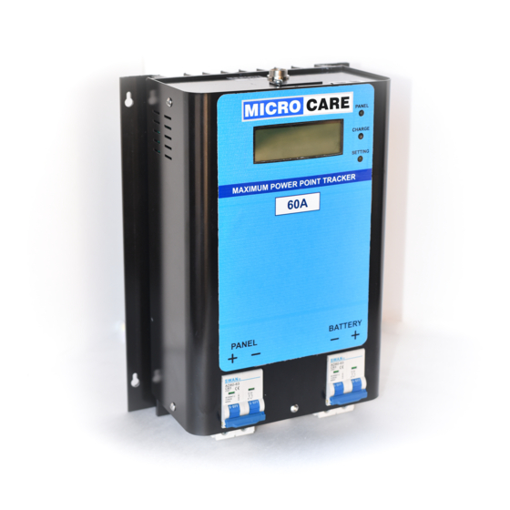
MPPT OVERVIEW MPPT OVERVIEW Fig 2.1: MPPT Front View Fig 2.2: MPPT Side View Fig 2.3: MPPT Top View Description Green Panel LED Green Charge LED Green Setting LED LCD Display Ventilation Holes Panel Circuit Breaker Battery Circuit Breaker Fig 2.4: MPPT Bottom View RJ12 Programming Port For Factory Programming Only Communications Port... -
Page 13: Mppt Installation
MPPT INSTALLATION MPPT INSTALLATION MPPT minimum installation clearance distance Fig 3.1: Minimum clearance distance Wall 20cm 20cm 20cm 20cm 20cm Cable Trunking Maintain a minimum clearance of 20cm below and around the MPPT to ensure unhindered air circulation. Mount the solar charge controller as close as possible to the batteries. MPPT Installation Instructions: •... -
Page 14: Lcd Mppt Installation Diagram
MPPT INSTALLATION LCD MPPT Installation Diagram 150mm Airflow 4 x ANSI B18.6.5M - M6x1 x 20 Cross Recessed Pan Head Self Tapping Screws 143mm 204mm 150mm Table 3.1: MPPT Mounting Hole Dimensions MPPT Height Width 20 Amp LCD MPPT 143 mm 204 mm 40 Amp LCD MPPT 143 mm... -
Page 15: Maximum Array Sizes
MPPT INSTALLATION Maximum Array Sizes The following should be used as a guide to the maximum array size that can be connected to the MPPT. The current limits to the specified level of the MPPT model so any array larger than these will simply waste power: Table 3.2: Maximum Photovoltaic Array Sizes in Watts Battery Set... - Page 16 MPPT INSTALLATION The voltage of the PV array may not exceed 150V and depending on the MPPT model, a specified current strength. The Battery Set array is however unlimited in size although an increase in Battery Set array capacity will increase the amount of time needed to fully charge the batteries. This complex setup diagram of a PV-MPPT System illustrates two 120V DC PV Arrays connected in parallel and two 48V DC Battery Sets connected in parallel This setup may be extended to suit the needs of the user.
-
Page 17: Wiring Information
WIRING INFORMATION WIRING INFORMATION Cable Sizes The PV (Photo Voltaic) panels should always be connected in the highest voltage configuration. The advantage of this is that panel current will always be at its minimum so that thinner connecting wires may be used which reduces voltage drops with loading and improves cost efficiency. The cable length from the batteries to the MPPT should not exceed 3m. -
Page 18: Battery Connection Methods
WIRING INFORMATION Battery Connection Methods 4.2.1 Series Connection 12V + 12V + 12V + 12V = 48V Ah remain at 100 Ah Series Connection (Voltage increases, amperage stays the same as a single battery) 4.2.2 Parallel Connection Voltage remains at 12V 100 Ah + 100 Ah + 100 Ah + 100 Ah = 400 Ah Parallel Connection (Voltage stays the same as a single battery, amperage increases) 4.2.3... -
Page 19: Basic Mppt Wiring Diagram Examples
WIRING INFORMATION Basic MPPT Wiring Diagram Examples PV Panel MPPT Charge Battery Inverter Controller The total array power is the sum of the power of all the panels connected in series and parallel. 4.3.1 2 x Panels Connected in Series For the example above: PV Panel specifications Maximum power:100W... -
Page 20: Panels Connected In Parallel
WIRING INFORMATION 4.3.2 2 x Panels Connected In Parallel For the example above: PV Panel specifications Maximum power: 310W Maximum power voltage (Vmp): 37V Maximum power current (Imp): 8,38A Open circuit voltage (Voc): 45V Short circuit current (Isc): 8,80A 2 x 310 W panels connected in parallel = 620W 2 x 12V 100Ah batteries in series = 24V 100Ah Recommended MPPT as per table 3.2 = 40A MPPT charge controller For the PV Parallel connection the voltage remains the same... -
Page 21: Connecting 2 X Mppt's In Parallel
WIRING INFORMATION Connecting 2 x MPPT’s in Parallel 4.3.4 This configuration can be used when connecting 2 arrays to one battery bank. -
Page 22: Basic System Diagram
WIRING INFORMATION Basic System Diagram... -
Page 23: V1 Lithium Ion Interface - Freedom Won Bms Wiring Diagram
WIRING INFORMATION V1 Lithium Ion Interface – Freedom Won BMS Wiring Diagram 4.5.1 Wiring Designation WIRE COLOUR MPPT WIRE FUNCTION MPPT PIN NUMBER Solar Charge Controller Enable (NO) TURQUIOSE Solar Charge Controller Enable (COM) WIRE COLOUR INVERTER WIRE FUNCTION INVERTER PIN NUMBER YELLOW Inverter Enable (NO) -
Page 24: V2 Lithium Ion Interface - Freedom Won Bms Wiring Diagram
WIRING INFORMATION V2 Lithium Ion Interface – Freedom Won BMS Wiring Diagram 4.6.1 100A MPPT and Inverter 4.6.2 60A MPPT and Inverter... -
Page 25: V2 Lithium Ion Interface - Solar Md Logger Wiring Diagram
WIRING INFORMATION V2 Lithium Ion Interface – Solar MD Logger Wiring Diagram 4.7.1 100A MPPT and Inverter 4.7.2 60A MPPT and Inverter... -
Page 26: V1 Lithium Ion Interface With No Bms
WIRING INFORMATION V1 Lithium Ion Interface With No BMS If the Lithium Ion battery has no BMS installed connect: MPPT with Interface • Connect the Purple wire to the Red wire to enable charging. Inverter with Interface • Connect Yellow wire to the Blue wire to enable the load. •... -
Page 27: V2 Lithium Ion Interface With No Bms
WIRING INFORMATION V2 Lithium Ion Interface With No BMS Ensure that the 4pin termination plug is inserted in the MPPT and Inverter. -
Page 28: Mppt Operation
MPPT OPERATION MPPT OPERATION Front Panel Description 9 10 Description Panel LED Charge LED Setting LED LCD Display Data Button Charge Button Panel Circuit Breaker Battery Circuit Breaker RJ12 - Do Not use RJ12 – External Connection Button Function Description Button Name Function description Data... -
Page 29: Checks Prior To Start-Up
MPPT OPERATION Checks Prior To Start-Up • Ensure the MPPT is mounted vertically. • Check input output cables are secured. • Check the polarity of the panel and battery and they are correct. • Check if the Panel Voltage meets the MPPT rating required. MPPT Start-up Procedure •... -
Page 30: Lcd Mppt Operation
Should the battery voltage shown be 12 volt system incorrect it is possible to force the MPPT to accept a new ....battery value. MICROCARE MPPT 40Amp The screen changes to Panel is LOW . . . MPPT sleeping . . . -
Page 31: Float Mode
LCD MPPT OPERATION There are other details that will appear on the screen that will assist the user to read at what point the MPPT and batteries are Float Mode BATTERY = 13.8 V FLOAT AT = 1.0 A flashing next to the BATTERY indicates that the MPPT is in FLOAT mode and the batteries are full. -
Page 32: Checking The Mppt Firmware
2 seconds and then automatically revert to the main screen: Check the Microcare website for the latest firmware available for your specific MPPT. To request a firmware upgrade for the MPPT, visit Microcare at www.microcare.co.za and contact them via the online email. -
Page 33: Setup Menu Settings
SETUP MENU SETTINGS SETUP MENU SETTINGS Setup Menu - Quick Reference Guide Menu Settings 12.4V – 14.5V FLOAT CHARGE VOLTAGE =13.8V DEFAULT 0.1V Increments 13.5V – 16V BOOST CHARGE VOLTAGE =14.5V DEFAULT 0.1v Increments BOOST TO FLT CHANGE Disabled, 10min, 30min, INTERVAL SCAN =10min 1hr,2 hrs, Default = 10 min... -
Page 34: Programming The Mppt
The Battery Circuit Breaker must be turned ON The Panel Circuit Breaker must be turned OFF When the Panel circuit breaker is turned off the MICROCARE MPPT 40Amp MPPT will enter the sleep mode and the MPPT must be in Panel is LOW SLEEP MODE to enter the programming mode . -
Page 35: Boost Voltage
Programming the MPPT Boost Voltage BOOST CHARGE VOLTAGE = 14.5v DEFAULT The Boost voltage can be changed between 13 and 16.0 volts press CHRG to save in 0.1 volt increments per 12V battery pack. press DATA to change Default Value is 14.5V. Obtain the correct boost charge voltage from your battery supplier ➢... -
Page 36: Battery Set Voltage
Programming the MPPT The display changes to: BATTERY PACK SELECT BATTERY PACK SELECT Battery Set Voltage 12 – 48 AUTO SELECT This allows the MPPT to auto select the battery system or the MPPT can be PRESET. press CHRG to save press DATA to change •... -
Page 37: Change Time Settings
Programming the MPPT ➢ Press the <CHARGE> button to save the setting The screen changes to: SET HOUR OF THE DAY 8.11 Change time settings SET HOUR OF THE DAY This allows the user to change the time settings of the MPPT. = 14: 40 The Hour of the day is changed in this screen through a 24hour time format with 1 hour increments. -
Page 38: External Connections
It also disconnects the load at the set low battery disconnect voltage and reconnects the load at the set reconnect voltage. • Note: The external output is only to be used with MICROCARE MPPT CHARGER accessories such as the Microcare Programmable Relay. Solar Assist signal The SOLAR ASSIST SIGNAL switches the relay for 10 seconds when the MPPT switches from BOOST to FLOAT. -
Page 39: Load Reconnect Voltage
EXTERNAL CONNECTIONS The following screen will appear: LOAD RECONNECTING @ = 13.0V PER BAT PACK 9.3.2 Load Reconnect Voltage press CHARGE to save If this is complete then the LOAD SHED RECONNECT voltage press DATA to change can be programmed which can be between 12-14 volts per pack: ➢... -
Page 40: To Reset The Mppt To Factory Defaults
EXTERNAL CONNECTIONS To reset the MPPT to factory defaults To reset the MPPT to factory defaults you need to make sure the MPPT Battery and Panel Breaker is off. Press and hold the DATA and CHARGE Button and turn on the battery breaker. The following screen will appear DO NOT PREES BOTH Once the countdown completes then the MPPT will have been... -
Page 41: Troubleshooting
• If the voltage is immediately dropping to the battery voltage then the MPPT needs to be sent to Microcare for repair. • If the voltage is not adjusting then you need to open up the MPPT and check the internal cables to confirm if the circuit breaker attachments are tight. -
Page 42: Output Short Circuit
Maintenance and service 10.5 Output Short Circuit This error message will be displayed if the load being drawn from the batteries is exceeding the amount of power that ERR DETECTED! the MPPT is capable of supplying. MPPT OUTPUT SHORT CIRCUIT If the load being drawn from the batteries is eg: 70A and you MPPT CHARGE DISABLED only... -
Page 43: Lcd Mppt Specifications
LCD MPPT SPECIFICATIONS LCD MPPT SPECIFICATIONS Nominal Battery Voltage Multi-Voltage (Automatic/Manual selection of voltage - 12/24/36/48V battery set) PV Input Voltage Open Circuit Absolute Maximum 150VDC Charge Algorithm 5-stage, 3-level Equalize/Boost/Float Equalize Voltage Charges12V to 15V per 12V DC battery pack for 1hour 13V –... -
Page 44: Lcd Mppt Accessories
LCD MPPT ACCESSORIES LCD MPPT ACCESSORIES 13.1 Data acquisition software 13.2 Battery Monitor 13.3 Battery Monitor Accessories 13.3.1 100 A Battery Sensor 13.3.2 200 A Battery Sensor 13.3.3 400 A Battery Sensor 13.3.4 Web-Logger 13.3.5 232-485 Converter 13.4 Programmable Relay 13.5 PV String Combiner and Surge Protection Box Available in multiple configurations... - Page 45 Removal of serial numbers may void the warranty. All remedies and the measure for damages are limited to the above. Microcare shall in no event be liable for consequential, incidental, contingent or special damages, even if having been advised of the probability of such damages.
- Page 46 3. The reason for the return. 4. Microcare must be notified within 7 days of your intention to return the goods which were purchased. 5. All items returned will be inspected prior to refund. If our technicians are not immediately available, the goods will have to be left with us until such time as a technician is available to check the items.
- Page 47 REGISTRATION OF MY MICROCARE PRODUCT Please register your product online at www.microcare/register-my-product Also complete the form below as a hardcopy reference for technical support. Product Serial Number: Product Description: Date Purchased Where was the product purchased. Company Name Contact Person...
Need help?
Do you have a question about the LCD MPPT 20 and is the answer not in the manual?
Questions and answers