Table of Contents
Advertisement
Advertisement
Table of Contents

Summary of Contents for Miyachi Unitek UNIFLOW 2
- Page 1 Artisan Technology Group is your source for quality new and certified-used/pre-owned equipment SERVICE CENTER REPAIRS WE BUY USED EQUIPMENT • FAST SHIPPING AND DELIVERY Experienced engineers and technicians on staff Sell your excess, underutilized, and idle used equipment at our full-service, in-house repair center We also offer credit for buy-backs and trade-ins •...
- Page 2 OPERATOR MANUAL 990-228 Revision D September 2007 ® UNIFLOW PULSED THERMODE CONTROL (BIPOLAR LOGIC) MODEL NUMBERS 1-292-01 1-292-01-01 1-292-01-02...
-
Page 3: Revision Record
Copyright © 2003 Unitek Miyachi Corporation The engineering designs, drawings and data contained herein are the proprietary work of UNITEK MIYACHI CORPORATION and may not be reproduced, copied, exhibited or otherwise used without the written authorization of UNITEK MIYACHI CORPORATION. Printed in the United States of America. -
Page 4: Table Of Contents
CONTENTS Page Revision Record ............................ii Contents .............................. iii Contact Us .............................. vi Safety Precautions ............................ vii Chapter 1. Description Section I: Features ..........................1-1 Overview ............................1-1 Control Models ..........................1-2 Heads, Thermodes and Accessories ....................1-2 Section II: Controls and Indicators ......................1-3 Front Panel ............................ -
Page 5: Contents
Contents (Continued) Page Chapter 3. Using Programming Functions Overview ............................3-1 Front Panel Display ..........................3-1 Run Mode ............................3-1 Setup Mode ............................3-2 Graph Key ............................3-2 Preheat ............................3-2 Rise ............................3-2 Reflow ............................3-3 Cool ............................3-3 Profile Number .......................... - Page 6 Page Chapter 4. Operating Instructions Section I: Introduction ........................... 4-1 Preparation ............................4-1 General Operator Safety ........................4-1 Section II: Operating Instructions ......................4-2 Powering Up ............................ 4-2 Pre-Defined Profiles ........................4-2 Direct Input ............................4-3 Chapter 5. Maintenance Section I. Before You Start Precautions ............................
-
Page 7: Contact Us
CONTACT US ® ® Thank you for purchasing a Unitek Miyachi Uniflow 2 Pulsed Thermode Control. Upon receipt, please inspect it thoroughly for shipping damage before you install it. If there is any damage, contact the shipping company immediately to file a claim, and notify Unitek Miyachi at: Unitek Miyachi 1820 South Myrtle Avenue P.O. -
Page 8: Safety Precautions
SAFETY PRECAUTIONS General This instruction manual describes the operation and maintenance of the Control and provides instructions relating to its safe use. Procedures described in this manual must be performed as detailed by Qualified and Trained personnel. For Safety, and to effectively take advantage of the full capabilities of the Control, please read this instruction thoroughly before attempting to use it. - Page 9 Before using this equipment, read the SAFETY PRECAUTIONS carefully to understand the correct usage of the equipment. x These precautions are given for safe use of the equipment and for prevention of injury to operators or others. x Be sure to read each of the instructions, as they are all important for safe operation.
- Page 10 WARNING Do NOT put your hands or fingers on the Thermode. When soldering, keep your hands and fingers away from the thermode. Do NOT touch any soldered part or Thermode during, or just after reflow soldering. The soldered parts and the Thermode are very hot. If you touch them you may be burned. Ground the equipment.
- Page 11 CAUTION Apply the specified source voltage. Applying the wrong voltage can cause fire and electrical shock. Keep water and water containers away from the Control. Water spilled on the Control can cause a short circuit, electrical shock, or fire. Use proper tools (wire strippers, pressure wire connectors, etc.) for terminations of the connecting cables.
-
Page 12: Chapter 1. Description Section I: Features
CHAPTER 1 DESCRIPTION Section I: Features Overview ® For the rest of this manual, the Uniflow 2 Pulsed Thermode• Control will simply be referred to as the Control. This manual describes the most common or “typical” components and options. If you have questions about custom items in your Control that are not covered in this manual, contact Unitek Miyachi using the phone, e-mail, or mailing information in the Foreword of this manual. -
Page 13: Control Models
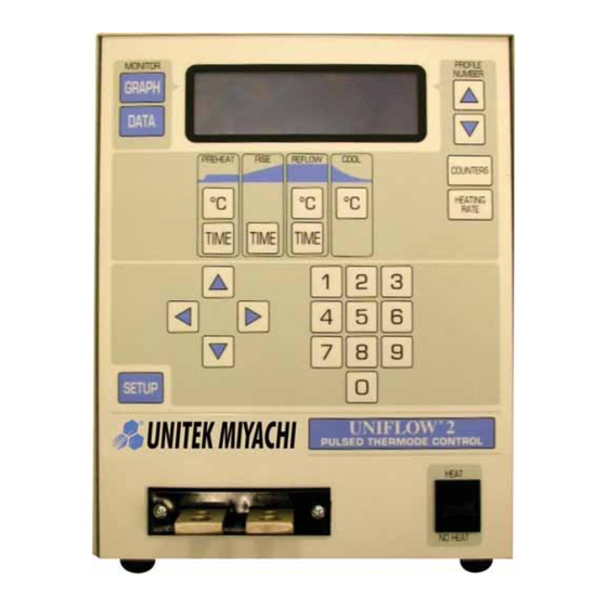
CHAPTER 1: DESCRIPTION Control Models The standard model of the Control has a front panel with controls and a display for operator control of the Control. AC Input Output Heating Model/Part # Type of Operation Voltage Capability Front panel. Has front panel controls and display for 2 KVA 1-292-01 local operator programming. -
Page 14: Section Ii: Controls And Indicators
5. COPY PROFILE 3. REFLOW SETUP NUMBER Select an item, Graph or Data Graphic Data Alphanumeric Data NOTE: These screens, their functions and displays are described in Chapter 3, Using Uniflow 2™ Programming Functions. ® UNIFLOW 2 PULSED THERMODE CONTROL... -
Page 15: Keypad
CHAPTER 1: DESCRIPTION Keypad The keypad allows you to edit the numeric values of the display screens. Cursor Keys The cursor keys allow you to move the editing cursor up, down and sideways. You use the (Up) and (Down) keys to select multiple pages in a single menu or setup screen. -
Page 16: Data Key
CHAPTER 1: DESCRIPTION DATA Key key brings up the data screen to the display. DATA The data screen reports the most recent heat TEMPERATURE: Thermode = 40qC cycle parameters in numerical format: time, Peak= 354qC Final=351qC Average = 349qC temperature, duty cycle, and counter status TIME: (Seconds) Preheat =01.0 Rise = 01.0 Heat= 03.0... -
Page 17: Data Edit Keys
CHAPTER 1: DESCRIPTION DATA EDIT Keys The data edit keys allow you to edit the time and temperature parameters of the heat profile on the graphic display. The keys are vertically PREHEAT RISE REFLOW COOL aligned with the profile heating states as displayed on the graphic screen. -
Page 18: Heat/No Heat Switch
CHAPTER 1: DESCRIPTION HEAT / NO HEAT Switch When this switch is in the position, the programmed profile can initiate HEAT heating energy. When you set the switch to the position, no heating current can flow. NO HEAT This function is required to adjust a new thermode to the work pieces prior to initiating a heating cycle. -
Page 20: Chapter 2. Installation And Setup Section I: Planning For Installation
CHAPTER 2 INSTALLATION AND SETUP Section I: Planning for Installation Space Requirements Dimensions (including all projections from the housing, but excluding cabling): 12.5 inches (317 millimeters) Height: Width: 10 inches (254 millimeters) Depth: 20.75 inches (527 millimeters) Weight: 4 KVA models: 58 pounds (26.3 kilograms) 2 KVA models: 46 pounds (20.86 kilograms) -
Page 21: Section Ii: Connections To External Equipment
CHAPTER 2: INSTALLATION AND SETUP Section II: Connections To External Equipment Overview All connections, other than the transformer cable connections, between the Control and external equipment are made through the rear panel. The transformer cable connections from the reflow soldering or heat seal head are made at the transformer cable terminals on the front panel. NOTE: If you require compressed air, cover gas, and cooling water service for the reflow soldering or heat seal head, please refer to the head manufacturer’s user’s manual for service specifications. -
Page 22: Input Power Connections
Input Power Connections CAUTION Be sure that the source power is appropriate for your Uniflow 2 Control model. Connect the Control power cable to a single-phase, 50/60Hz power source. The nominal voltage range for each model is set at the factory: either 100 to 120 VAC, or 208 to 240 VAC. - Page 23 CHAPTER 2: INSTALLATION AND SETUP Connect the two transformer cables from the head to the transformer terminals on the Control front panel. ® UNIFLOW 2 PULSED THERMODE CONTROL 990-228...
-
Page 24: Section Iii: Equipment Setup
CHAPTER 2: INSTALLATION AND SETUP Section III: Equipment Setup Force Fired, Mechanically Actuated Head 1. Adjust the reflow soldering head force adjustment knob to produce 5 units of force, as displayed on the force indicator index. Connect the reflow soldering head firing switch cable connector to the Control firing switch cable connector. -
Page 25: Force Fired, Air Actuated Head
CHAPTER 2: INSTALLATION AND SETUP Force Fired, Air Actuated Head 1. Adjust the head force adjustment knob to produce 5 units of force, as displayed on the force indicator index. Connect the head firing switch cable connector to the Control firing switch cable INITIATE connector. - Page 26 CHAPTER 2: INSTALLATION AND SETUP Connect a properly filtered air line to the air inlet fitting on the head. Use 0.25 inch O.D. by 0.17 inch I.D. plastic hose with a rated burst pressure of 250 psi. Limit the length of the air line to less than 40 in.
-
Page 28: Chapter 3. Using Programming Functions
CHAPTER 3 USING PROGRAMMING FUNCTIONS Overview To ensure accurate, consistent soldering, the Control delivers extremely precise pulses of energy to the reflow head. Each pulse is comprised of time and energy values pre-programmed by the user. Chapter 1, Description told you where the Controls and Indicators are located. This chapter describes how to use them in order to program the precise temperature profiles needed for reflow soldering or heat sealing electronic interconnections. -
Page 29: Setup Mode
® CHAPTER 3: USING UNIFLOW 2 PROGRAMMING FUNCTIONS Setup Mode Press the key to enter the setup mode. In SETUP < SETUP MENU > the setup mode, the display presents system 1. HARDWARE SETUP 4. SYSTEM SECURITY setup options for you to select. 2. -
Page 30: Reflow
® CHAPTER 3: USING UNIFLOW 2 PROGRAMMING FUNCTIONS Reflow You use the period to actually melt the solder for a reflow solder joint, or set thermoplastic or Reflow thermoset conductive adhesives for a heat-seal joint. NOTE: The Reflow temperature will always be higher than the actual melting point of the solder or heat seal adhesives due to heat losses in both the thermode and parts. -
Page 31: Counters Key
® CHAPTER 3: USING UNIFLOW 2 PROGRAMMING FUNCTIONS PROFILE NUMBER Keys With the graphics screen on the display, these keys will increment/decrement the heat profile number on the graphics screen. With the data screen on the display, pressing either key returns the graphics screen to the display; PROFILE NUMBER the keys will then increment/decrement the profile number on the screen. -
Page 32: Replace Counter
® CHAPTER 3: USING UNIFLOW 2 PROGRAMMING FUNCTIONS Replace Counter Press the key to edit the replace counter. The count that you enter will raise an alarm to signal the operator that it is time to replace the thermode. Thermodes ultimately fail due to repeated heat cycles that cause internal cracking, slowing down heat generation in the thermode. -
Page 33: Heating Rate Key
® CHAPTER 3: USING UNIFLOW 2 PROGRAMMING FUNCTIONS HEATING RATE Key key brings up the screen. This screen HEATING RATE MANUAL TUNING allows you to go to the SET COARSE HEATING RATE SET FINE HEATING heating rate capability to match the heat generating capability of the RATE thermode to minimize the temperature overshoot and undershoot. -
Page 34: Setup Key
® CHAPTER 3: USING UNIFLOW 2 PROGRAMMING FUNCTIONS Refer to the bottom line of the display. The contents are prompts (instructions) for editing and exiting the screen. You will find operation-specific instructions like these on every menu screen. The highlighted word or symbol indicates the key you must press to perform the operation listed next to the highlighted word or symbol. -
Page 35: Hardware Setup
® CHAPTER 3: USING UNIFLOW 2 PROGRAMMING FUNCTIONS HARDWARE SETUP, Page 1 Pressing with the screen SETUP MENU < HARDWARE SETUP, page 1 of 2 > displayed will bring up of the Page 1 1. HEAD COOL VALVE IS : OFF 2. -
Page 36: List Of Hardware
® CHAPTER 3: USING UNIFLOW 2 PROGRAMMING FUNCTIONS LIST OF HARDWARE, Page 1 Press the key to bring up the AUTO < AUTO RECOGNIZED HARDWARE > screen. This screen RECOGNIZED HARDWARE a. MANUAL HEAD IS CONNECTED b. LINE FREQUENCY DETECTION IS : 60HZ lists the system software-recognized hardware c. -
Page 37: Set Output Relays
® CHAPTER 3: USING UNIFLOW 2 PROGRAMMING FUNCTIONS SET OUTPUT RELAYS, Page 2 Press the key to bring up the screen. RELAY < RELAY > screen allows you to select the RELAY 1. RELAY 1: NC WHEN ALARM 2. RELAY 2: NC WHEN ALARM Alarm for Status actuation states or each relay. -
Page 38: Communications
® CHAPTER 3: USING UNIFLOW 2 PROGRAMMING FUNCTIONS COMMUNICATIONS key returns you to the screen. The key on the brings up the SETUP SETUP MENU SETUP MENU screen. COMMUNICATION < COMMUNICATION > COMMUNICATION ROLE 1. COMMUNICATION ROLE : MASTER Press the key to toggle between MASTER 2. - Page 39 ® CHAPTER 3: USING UNIFLOW 2 PROGRAMMING FUNCTIONS With the screen displayed, press SETUP MENU < SETUP MENU > key to bring up of the Page 1 REFLOW 1. HARDWARE SETUP 4. SYSTEM SECURITY 2. COMMUNICATIONS 5. COPY PROFILE screen. TEMPERATURE SETUP 3.
-
Page 40: Reflow Temperature Setup
® CHAPTER 3: USING UNIFLOW 2 PROGRAMMING FUNCTIONS Lower Temperature Limit only covers the Lower Temperature Limit Reflow period as shown on the right. The actual temperature must be above the lower -50qC temperature limit by the end of the Reflow period to avoid triggering the alarm. -
Page 41: Set Safety Timer
® CHAPTER 3: USING UNIFLOW 2 PROGRAMMING FUNCTIONS SET SAFETY TIMER Press the to bring up the SET SAFETY TIMER < SET SAFETY TIMER > . Use the safety timer to abort the SCREEN SET SAFETY TIMER : 00 reflow cycle if temperature has not risen to the temperature set point by the time set in the safety timer. -
Page 42: System Security
® CHAPTER 3: USING UNIFLOW 2 PROGRAMMING FUNCTIONS SYSTEM SECURITY From the screen the key will SETUP MENU < SETUP MENU > bring up the screen. SYSTEM SECURITY 1. HARDWARE SETUP 4. SYSTEM SECURITY 2. COMMUNICATIONS 5. COPY PROFILE 3. REFLOW SETUP NUMBER Select an item, Graph or Data This screen allows you to... -
Page 44: Preparation
CHAPTER 4 OPERATING INSTRUCTIONS Section I: Before You Start Preparation Before operating the Control: You must be familiar with the principles of reflow soldering. You must be familiar with the location and function of Controls and Indicators. For more information, see Chapter 1, Description. Verify that all equipment has been connected properly. -
Page 45: Powering Up
CHAPTER 4: OPERATING INSTRUCTIONS Section II: Operating Instructions Powering Up To turn the Control power ON, set the circuit breaker/power switch on the rear panel to the ON 40°C position. After two introductory screens are displayed, the screen will be SYSTEM READY SYSTEM READY displayed. -
Page 46: Direct Input
CHAPTER 4: OPERATING INSTRUCTIONS Direct Input CAUTION You can accidentally overwrite (erase) an existing stored profile when using the front panel controls. Before you start Direct Input, use the up/down PROFILE NUMBER keys to select a profile number that is “blank” or “expendable” to prevent overwriting a profile you want to keep. - Page 47 CHAPTER 4: OPERATING INSTRUCTIONS Press the key to select the time field for editing. Use the keypad to enter a RISE TIME RISE time to 1.5 (1.5 seconds), then press the key. RISE GRAPH REFLOW qC 6. Press the key to select the temperature value for editing.
-
Page 48: Chapter 5. Maintenance
CHAPTER 5 MAINTENANCE Section I. Before You Start Precautions DANGER DEATH may result from contact with lethal voltages inside the Control. Never attempt to repair the Control with power applied. Turn power to the unit OFF before starting maintenance work. Tag (and preferably lock) the switch so that power is not accidentally restored. -
Page 49: Section Ii. Troubleshooting
CHAPTER 5: MAINTENANCE Section II. Troubleshooting Alarm Message Description Corrective Action ABORT REFLOW: Decrease Actual thermode temperature exceeded Set Course Heating Rate one setting Heating Rate the HI LIMIT value. slower. Increase the HI LIMIT value. Increase the Preheat Time. ABORT REFLOW: Firing When the FOOTSWITCH Lift the footswitch all the way up and... - Page 50 CHAPTER 5: MAINTENANCE Alarm Message Description Corrective Action FIRING SWITCH NOT Air Actuated Reflow Soldering Head Initiate another reflow process cycle. ACTUATED Firing Switch has not actuated. Switch Increase Air Actuated Reflow must actuate within 10 seconds after Soldering Head air pressure until initiating a new reflow process cycle.
- Page 51 CHAPTER 5: MAINTENANCE Alarm Message Description Corrective Action REFLOW ALARM: Increase Actual thermode temperature never Set Course Heating Rate one setting Heating Rate reaches the LOW LIMIT value during faster. the Reflow time period. Increase the LOW LIMIT value. Increase the Preheat Time. Check cables between the Control output and the Reflow Soldering Head for loose connections.
-
Page 52: Section Iii. Maintenance
CHAPTER 5: MAINTENANCE Section III. Maintenance Thermode Maintenance When a heat profile has been suitable for a particular application over many bonds, but poor quality bonds are now resulting, thermode surface deterioration could be the problem. If you need to increase heat period temperature and time to maintain the same bond quality, the thermode surface is probably coated with heavy flux, adhesive or polyimide ribbon flex cable residue. -
Page 54: Chapter 6. Calibration
CHAPTER 6 CALIBRATION Overview This reflow equipment does not use internal calibration adjustments. High precision temperature capturing electronics is used which does not drift with age or use. This procedure allows the user to verify the calibration condition of the unit. Any out-of-calibration condition can only be caused by an internal part failure on the main board and can only be remedied by replacing the broken part. -
Page 56: Appendix A. Technical Specifications
APPENDIX A TECHNICAL SPECIFICATIONS Electrical Mains AC Voltage Ranges: Model 1-292-01 ..................... 90 to 132 VAC Models 1-292-01-01 & 1-292-01-02 ..............180 to 264 VAC Line Frequency .........................50 or 60 Hz Line Phase ..........................Single Input Circuit Breaker Rating .....................15 A Power Cord Connection .............European CE Harmonized Wiring Code, or NEMA Wiring Code Environment... - Page 57 Heat Profile Select ..............Select 15 heat profiles using four inputs activated in a binary coded pattern Operator Initiation Switch..............1-level or 2-level foot switch Heat Initiation Sensor ............. Heat force or Uniflow 2 head down sensor for initiating thermode heating No Heat Switch......................Heat only inhibit Emergency Stop (CE Requirement).............
-
Page 58: Contact Rating
Model 1-292-01 ........................2.0 KVA Models 1-292-01-01 & 1-292-01-02 ................4.0 KVA Solid State Relays: Power (Uniflow 2 control provided) ............24 VAC or +24 VDC Contact Rating ..................24 VAC/24 VDC, 0.3 A Head Cool Valve ..............ON/OFF for cooling thermode holder Solder Cool Valve .......... - Page 60 APPENDIX B ELECTRICAL AND DATA CONNECTIONS RS-232 Connections #1 --.No Connection #6 – Data Terminal Request #2 --. RS-232 Transmit #7 – Clear To Send #3 – RS-232 Receive #8 – Request To Send #4 – Data Set Ready #9 – Ring Indicator #5 –...
-
Page 61: Appendix B. Electrical And Data Connectors
APPENDIX B: ELECTRICAL AND DATA CONNECTIONS Negative/Positive Logic Operation Your Control is factory-configured for positive logic, active low. That is, when an input terminal is unterminated, an internal resistor pulls the input terminal to a positive voltage and the input terminal is considered to be inactive. - Page 62 APPENDIX B: ELECTRICAL AND DATA CONNECTIONS Control Input Interface NOTE: The may be connected to a PLC or other interface in the configurations Control Input Interface shown on pages B-4 £ B-9. ® UNIFLOW 2 PULSED THERMODE CONTROL 990-228...
- Page 63 APPENDIX B: ELECTRICAL AND DATA CONNECTIONS Switch Contact Input (Internal Power) ® UNIFLOW 2 PULSED THERMODE CONTROL 990-228...
- Page 64 APPENDIX B: ELECTRICAL AND DATA CONNECTIONS Switch Contact Input (External Power) ® UNIFLOW 2 PULSED THERMODE CONTROL 990-228...
- Page 65 APPENDIX B: ELECTRICAL AND DATA CONNECTIONS Common Negative Input (Internal Power) ® UNIFLOW 2 PULSED THERMODE CONTROL 990-228...
- Page 66 APPENDIX B: ELECTRICAL AND DATA CONNECTIONS Common Negative Input (External Power) ® UNIFLOW 2 PULSED THERMODE CONTROL 990-228...
- Page 67 APPENDIX B: ELECTRICAL AND DATA CONNECTIONS Common Positive Input (Internal Power) ® UNIFLOW 2 PULSED THERMODE CONTROL 990-228...
- Page 68 APPENDIX B: ELECTRICAL AND DATA CONNECTIONS Common Positive Input (External Power) ® UNIFLOW 2 PULSED THERMODE CONTROL 990-228...
- Page 69 APPENDIX B: ELECTRICAL AND DATA CONNECTIONS Force Valve Drive Connections Valve Driver Outputs 24 VAC/VDC, 0.3 A max Output Rating: AC or DC 24 volt output power is selectable by connecting the proper Output Voltage Selection: plug as shown on the next page. NOTES: For AIR HEAD VALVE operation either (1) jumper HEAD VALVE CONNECTOR pin 2 and pin 4 or (2) jumper J4A pin 6 (AIR HEAD) to VALVE DRIVER COMMON or <0V OUT>...
- Page 70 APPENDIX B: ELECTRICAL AND DATA CONNECTIONS (Continued) To change from 24VAC output power to 24 VDC Output Voltage Selection: output power , unplug the white plug from the connector shown below and plug in the white plug. Timing: The force valve actuates when the first level of the foot switch is closed. It automatically de-activates when the temperature is reached, or COOL...
- Page 71 APPENDIX B: ELECTRICAL AND DATA CONNECTIONS Alarm/Status Relays Connections Relay Rating: 250 VAC or 30 VDC at 5 A User Programmable Options for Relay States: Reflow: ON/OFF during reflow process cycle Preheat: ON/OFF for continuous preheat (also known as the idle state) Alarm: ON/OFF for alarm conditions.
- Page 72 APPENDIX B: ELECTRICAL AND DATA CONNECTIONS Relay State Timing ® UNIFLOW 2 PULSED THERMODE CONTROL 990-228 B-13...
- Page 73 APPENDIX B: ELECTRICAL AND DATA CONNECTIONS Remote Selection with Switches or Opto-Couplers You may use either a 1-level or 2-level foot switch with the Control. Foot Switch Inputs: When using a 1-level foot switch, you must jumper the two-level inputs together so that the two levels operate as an OR-function, as shown in the Figure above.
- Page 74 APPENDIX B: ELECTRICAL AND DATA CONNECTIONS Automation Control Inputs Connections 0 or 24 VDC, 2 mA max Input Signal Rating: All Profiles must be entered and saved in the Control memory Remote Profile Inputs: locally (from the Front Panel). Once they are saved, they can be recalled prior to initiating the Reflow process by placing a binary value on the four lines.
- Page 75 APPENDIX B: ELECTRICAL AND DATA CONNECTIONS Operator Initiation Switch and Firing Switch Inputs 0 or 24 VDC, 2 mA maximum Input Signal Rating: ® UNIFLOW 2 PULSED THERMODE CONTROL B-16 990-228...
- Page 76 APPENDIX B: ELECTRICAL AND DATA CONNECTIONS EMERGENCY STOP Input 24 VDC at 2 mA maximum Input Signal Rating: Normally closed pushbutton Type of Switch: When the switch is pressed, it removes 24-volt Timing: EMERGENCY STOP power from the reflow head, causing it to retract immediately. Manual Alarm Reset Input Signal Rating: 0 to 24 VDC, 2 mA maximum...
-
Page 78: Appendix C. System Timing
APPENDIX C SYSTEM TIMING NOTE: All inputs are debounced for a fixed 30ms period. ® UNIFLOW 2 PULSED THERMODE CONTROL 990-228... - Page 80 APPENDIX D COMMUNICATION CODES Section I. Command Format COMMAND KEYWORDS: BOLD. italics. VARIABLE: {enclosed in braces} (one required and only one parameter REQUIRED PARAMETERS: allowed). separated by vertical bar " | " indicates one or another of choices CHOICE OF PARAMETERS: presented.
- Page 81 This terminates the transmission. (End transmit 0x04). Response to Errors or Unsupported Commands The UNIFLOW 2 will respond to the receipt of incorrect transmitted data with a NAK command under the following conditions. The format of the NAK command string is: <soh>...
-
Page 82: Appendix D. Communications
APPENDIX D: COMMUNICATION CODES When you issue a command to the Uniflow 2, you need to wait about 250 ms. before you issue the next command. The answer timeout is set to about 250 ms. in case the Uniflow 2 doesn’t respond to a command. - Page 83 APPENDIX D: COMMUNICATION CODES Significance of the unit’s RS232/485 SELECT parameter on the Communications screen: 1. RS-232 and RS-485 are mutually exclusive. One or the other is selected at the Communications screen. 2. The serial link to the host computer should be plugged into the proper socket on the back of the unit.
- Page 84 APPENDIX D: COMMUNICATION CODES Host Originated Command Set These are commands sent by the host computer, via the RS-485/RS-232 port to the UNIFLOW 2. NAME COMMAND DATA SIZE COPY “CP” Set Source schedule # 2 Bytes 1 Byte Destination schedule #...
- Page 85 APPENDIX D: COMMUNICATION CODES 12 = COPYSCR2 13 = COPYRIGHT 14 = DATASCR 15 = DEFAULTS 16 = (not used) 17 = FREQ_DETECT 18 = GOOD_REFLOW_CNTR 19 = GRAPHSCR 20 = HARDWARE1 21 = HARDWARE2 22 = HEATSWTEST 23 = HIDDEN 24 = HW_LIST 25 = KBDTEST 26 = KDSCR...
- Page 86 APPENDIX D: COMMUNICATION CODES PROFILE “DR” Read Profile # 2 Bytes “DS” Set ProfileNum (Profile number to be modified: 01 - 15) 2 Bytes 1 Byte PreheatTemp (Preheat temperature: 060 - 999) 3 Bytes 1 Byte ReflowTemp (Reflow temperature: 060 - 999) 3 Bytes 1 Byte CoolTemp (Cool temperature: 060 - 999)
- Page 87 APPENDIX D: COMMUNICATION CODES RESET “RX” Reset Resets system 0 Bytes SECURITY “SR” Read Read Security Locks 0 Bytes “SS” Set Password (0000000 – 9999999) 7 Bytes (Note: Password is not set by this command. It must match the password in the unit in order to set security locks below) 1 Byte ProfileLock (Profile Lock: 0 = OFF, 1 = ON) 1 Byte...
- Page 88 APPENDIX D: COMMUNICATION CODES UNIFLOW 2 Originated Response Command Set These are commands returned by the UNIFLOW 2, via the RS-485/RS-232 port. NAME COMMAND DATA SIZE COUNTER “CS” Set ReflowCntrs.dwTotalUsageCnt (Total Usage Cntr: 0000000 – 9999999) 7 Bytes 1 Byte ReflowCntrs.dwGoodReflowCnt (Good Rflo Cntr: 0000000 –...
- Page 89 APPENDIX D: COMMUNICATION CODES 21 = HARDWARE2 22 = HEATSWTEST 23 = HIDDEN 24 = HW_LIST 25 = KBDTEST 26 = KDSCR 27 = KISCR 28 = KPSCR 29 = LOGO_SCR 30 = LOWER_TEMP 31 = MANUAL_TUNING 32 = MAX_TEMP 33 = PASSWORD 34 = PIDPARAMS 35 = PIXELONTEST...
- Page 90 APPENDIX D: COMMUNICATION CODES 10 = REFLOW_BELOWPREHEAT 11 = ACCESSDENIED 12 = SETDEFAULTS 13 = FIRINGSWOPEN 14 = SAFETYTIMER 15 = FIRINGSWNOTACTIVATED 16 = DECREASEHEATINGRATE 17 = INCREASEHEATINGRATE 18 = REPLACE 19 = CLEAN 20 = REPLACERESET 21 = CLEANRESET 22 = POWERMODE 23 = NOHEATSWITCH 24 = PREHEATON...
- Page 91 APPENDIX D: COMMUNICATION CODES RELAY “VS” Relays1.on_off (0 = NORMALOPEN, 1 = NORMALCLOSED) 1 Byte 1 Byte Relays1.when 1 Byte REFLOW_TRIG = 0, PREHEATON_TRIG = 1 ALARM_TRIG = 2 CLEANTHERM_TRIG = 3 REPLACETHERM_TRIG = 4 ENDOFREFLOW_TRIG = 5 HEADACTIVE_TRIG = 6 SYSTEMREADY_TRIG = 7 NOTACTIVE_TRIG = 8 1 Byte...
- Page 92 APPENDIX D: COMMUNICATION CODES 11 = ACCESSDENIED 12 = SETDEFAULTS 13 = FIRINGSWOPEN 14 = SAFETYTIMER 15 = FIRINGSWNOTACTIVATED 16 = DECREASEHEATINGRATE 17 = INCREASEHEATINGRATE 18 = REPLACE 19 = CLEAN 20 = REPLACERESET 21 = CLEANRESET 22 = POWERMODE 23 = NOHEATSWITCH 24 = PREHEATON 25 = AUTOSCALE...
- Page 93 APPENDIX D: COMMUNICATION CODES UpperTempLimit (000 – 999) 3 Bytes 1 Byte LowerTempLimit (0 – 999) 3 Bytes 1 Byte AutoscalingEnabled (0 = OFF, 1 = ON) 1 Byte 1 Byte SafetyTimerTime (00 – 99) 2 Bytes 1 Byte ReleaseTimerTime (00 – 99) 2 Bytes 1 Byte MaxTempLimit (000 –...
- Page 94 APPENDIX D: COMMUNICATION CODES EXAMPLES: An example of sending a TYPE command to the Uniflow 2: <soh>”01TY0009E”<eot> The Unit’s address is “01” The command: “TY” The Count is: “000” The check sum is “9E”. Which is calculated from the ASCII (American Standard code for information interchange) and is a two charter ASCII HEX string calculated from the sum of all bytes except <soh>, <cksum>, and <eot>.
- Page 96 APPENDIX E GUIDELINES FOR REFLOW SOLDERING Overview This Appendix covers the process definition and components used in the pulse heated reflow soldering of flexible circuits to printed circuit boards. We will look in depth at the component part design criteria necessary to achieve the optimum quality and consistency of a flex to PCB assembly, concentrating on the most popular joint designs and component parts used in the process today.
- Page 97 APPENDIX E: GUIDELINES FOR REFLOW SOLDERING There are three common types of termination designs used on flex circuits for the pulse heated reflow process: The “exposed lead” design has both sides of the polyimide material removed, leaving the traces free of insulation. This allows the thermode to contact the traces directly, and conduct heat to the parts.
- Page 98 APPENDIX E: GUIDELINES FOR REFLOW SOLDERING Flex and PCB Trace Sizes Ideally, the flexible circuit pads should be narrower in width than that of the pads on the printed circuit board. As the solder melts and the parts compress, solder is forced to the side. This design will allow space for the solder to flow on either side of the flex pad and will be more tolerant of solder quantity on the PCB, avoiding solder bridging problems.
- Page 99 APPENDIX E: GUIDELINES FOR REFLOW SOLDERING A. Heat is easily transferred away from the joint area to the large landmass, which is positioned too near to the joint area. B. Increased trace width and plated through-hole draw heat from the joint area. C.
- Page 100 APPENDIX E: GUIDELINES FOR REFLOW SOLDERING A. A smaller screen aperture can provide 40% solder coverage of pad. B. Shows an alternate screen design. C. Resulting solder deposit prior to the reflow (IR) process. D. Solder is spread evenly across pad after the reflow (IR) process. Note smaller height profile. TARGET SOLDER SCREEN THICKNESS OPENING CHEM.NI/AU...
- Page 101 APPENDIX E: GUIDELINES FOR REFLOW SOLDERING TARGET SOLDER SCREEN THICKNESS OPENING CHEM.NI/AU Cu PASSIVE / PALLADIUM PAD SIZE AND VOLUME HOT AIR LEVEL PITCH mm³ / inches Microns / inches mm / inches mm / inches Mm/ inches 200 micron / 0.008” 0.4 x 1.4 / 0.016 x 0.055 0.4 x 2.0 / 0.016 x 0.055 100 micron / 0.004”...
- Page 102 APPENDIX E: GUIDELINES FOR REFLOW SOLDERING Flex Pad Width Note that the flex pad finishes short of the PCB pad. This is to allow easy inspection of the joint. PCB Pad Width Extra width allows for excess solder and ease of inspection. PCB pad is approximately three times the width of thermode.
- Page 103 APPENDIX E: GUIDELINES FOR REFLOW SOLDERING Thermode Manufacturing And Temperature Characteristics Modern wire erosion techniques such as EDM and advanced materials have allowed the manufacture of precisely designed thermodes to suit most applications. Three-dimensional thermodes pass the current around the face and thus have zero voltage potential across the traces. These technological advances in machining processes produce designs with constant temperature across the length, and special alloys achieve flatness and co-planarity under heating.
- Page 104 APPENDIX E: GUIDELINES FOR REFLOW SOLDERING Flux Flux has two important features. It conducts the heat to the solder and it promotes the wetting of the surfaces by cleaning and removal of surface oxides. For easy to solder parts, the pulse heated soldering process requires only a minimum of non-activated flux.
- Page 105 APPENDIX E: GUIDELINES FOR REFLOW SOLDERING Reflow The actual time and temperature can be programmed for this stage of the process. Time is programmable in 0.1-second increments and temperature in 1-degree increments. Typically, the temperature set point for an open solder joint with direct thermode contact to parts will be between 280 - 330qC.
- Page 106 APPENDIX E: GUIDELINES FOR REFLOW SOLDERING Quality Control And Inspection Pressure is maintained as the joint is cooled. Therefore there is little chance of a dry joint occurring. The imprint of the thermode should be seen on the solder joint and be even in width and length. There should be visual evidence that reflow has occurred and when the parts are peeled apart the resulting joint will have a granular appearance over the soldered area.
-
Page 108: Index
Overview ........... 1-1 Communication Codes ........D-1 Dimensions ............A-1 Command Format ...........D-1 Direct Input ............4-3 Uniflow 2 Communication Codes ....D-2 Display (LCD) ............ 1-3 Definition of Command Elements ....D-2 DISPLAY CONTRAST, Page 2 ......3-9 Host Originated Command Set ....D-4 Response to Errors or Unsupported Commands ......D-2... - Page 109 INDEX E (Continued) RS-232 Connections ........B-1 Control-to-Head Connections ....2-3 RS-485 Connections ........B-1 Input Power Connections ......2-3 Switch Contact Input (External Power) ..B-5 Overview ........... 2-2 Switch Contact Input (Internal Power) ...B-4 Equipment Setup ..........2-5 Valve Driver Outputs ........B-10 Force Fired, Air Actuated Head ....
- Page 110 INDEX Performance ............A-1 Switched Input Electrical Requirements ..A-2 Planning for Installation ........2-1 SYSTEM SECURITY ........3-14 Powering Up ............4-2 System Timing .............C-1 Precautions ............5-1 Pre-Defined Reflow Profiles ........4-2 Preheat ............3-2 Preparation ............4-1 Technical Specifications ........A-1 Present Temperature ..........3-3 Electrical Mains ..........
- Page 111 INDEX U (Continued Graph Key ............3-2 PROFILE NUMBER Keys ..... 3-4 Cool ............3-3 REFLOW TEMPERATURE SETUP, Preheat ............3-2 Page 2 ............3-13 Present Temperature ........3-3 Saving Changed Values ........3-5 Profile Number ...........3-3 SET OUTPUT RELAYS, Page 2....3-10 Reflow ............3-3 SET RELEASE TIMER .......
- Page 112 Artisan Technology Group is your source for quality new and certified-used/pre-owned equipment SERVICE CENTER REPAIRS WE BUY USED EQUIPMENT • FAST SHIPPING AND DELIVERY Experienced engineers and technicians on staff Sell your excess, underutilized, and idle used equipment at our full-service, in-house repair center We also offer credit for buy-backs and trade-ins •...
Need help?
Do you have a question about the UNIFLOW 2 and is the answer not in the manual?
Questions and answers