
Related Manuals for Electrothermal INTEGRITY 10


Summary of Contents for Electrothermal INTEGRITY 10
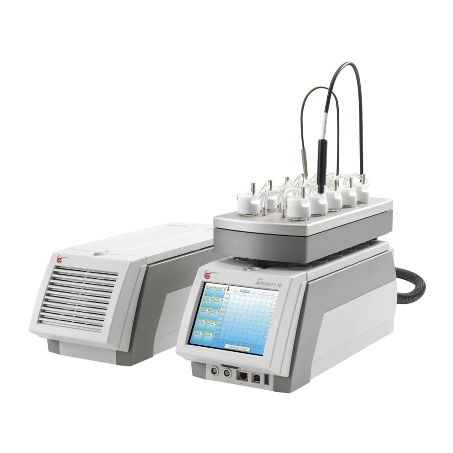
- Page 1 (Integrity 10 Reaction Station & Power Supply unit). INTEGRITY 10. REACTION STATION. PS20000 INSTRUCTION BOOK Page 1 of 80 M8024 Issue 3.4 For use with master product software V3.5.1.8 and above.
-
Page 2: Table Of Contents
Please take your time to read this Instructions book in order to understand the safe and correct use of your new Bibby Scientific product. It is recommended the Responsible Body for use of this equipment reads this Instruction book and ensures the user(s) are suitably trained in its operation. Section 1. - Page 3 In the interest of continued development Bibby Scientific Limited reserve the right to alter or modify the design and /or assembly process of their products without prior notification. This product is manufactured in Great Britian by Electrothermal, part of the Bibby Scientific Group of companies. Bibby Scientific Limited.
-
Page 4: Introduction
1.5. For standalone use the Integrity 10 is easy to set up using the touch screen. With an intuitive menu system, operation is both quick and simple allowing the user to set up and operate a simple profile or operate with full manual control. -
Page 5: Symbols And Using This Instruction Book
YMBOLS AND USING THIS INSTRUCTION BOOK. 2.1. Throughout this Instructions book the following symbols are shown which identify conditions that pose a hazard to the user or to identify actions that should be observed. These symbols are also shown on the product or its packaging. -
Page 6: Safety Information
Ensure the PSU is positioned on a clean, dry, non-combustible surface with a sufficient space for the power cable to Integrity 10 and mains input lead and plug set to enter / exit without undue bend stresses. Ensure a suitable clearance for air flow and heat dissipation. - Page 7 , hoods, PPI etc. for process being operated with due regard to use of glassware at pressures other than atmospheric. Test undertaken by Electrothermal Engineering on sample new glassware at ambient temperature, assembled with ATS10377 inerting cap, (tested under water) indicate withstand pressure of 0.5 bar gauge.
- Page 8 Silicone Cap Peroxide cross linked HTV silicone rubber, classified in accordance with ASTM D 1418 as Septum VMQ. Recommend check for specific chemicals by reference to internet search engine 316 Stainless Steel Recommend check for specific chemicals by reference to internet search engine. gas nozzle 316 Stainless steel Recommend check for specific chemicals by reference to internet search engine.
-
Page 9: Unpack And Contents
4. UNPACK AND CONTENTS. 4.1. Please check the contents of your carton against the diagram. Item Description Instruction book Integrity 10 - PSU Integrity 10 - UNIT Mains cord and lead set (illustration only) Stir bars (Pkt10) Power cable assembly... -
Page 10: Installation
Such testing will invalidate warranty. DC dielectric withstand (flash / Hi Pot) may be applied to the PSU only (i.e. The Integrity 10 unit must not be connected when the PSU is being tested. The Integrity 10 unit operates at low voltage (15V DC) and must not be subjected to dielectric withstand (Flash / Hi Pot) testing. - Page 11 PSU. 5.2. Mechanical Installation. To ensure efficient heating and cooling, the Integrity 10 cell design incorporates high quality copper heat sink components that ensure optimum heat transfer between the process and the cooling media.
-
Page 12: Environmental Protection
This product contains a Lithium Cell button Battery (CR2032) on the control PCB located in the front Pod of the Integrity 10 Unit. All batteries must be disposed of in accordance with regulations. Do Not dispose of product in a fire as batteries may explode. -
Page 13: Product Operation
7. PRODUCTION OPERATION. 7.1. Product overview. 7.1.1. The illustrations below show a detailed layout of the product. Integrity 10 Unit. Latch – Drip tray release Drip tray Reaction well Refer to Instruction book warning. Bus socket (for driving accessories). In / out coolant water supply. -
Page 14: Reduction Sleeves, Fitting Removal
7.2. Reduction Sleeves. Fitting and Removal. (Reduction sleeves are an accessory available to accommodate 24mm & 16mm diameter glassware – see Section 11). Always ensure the cell temperatures are at a safe to touch. (Between 40° and -5°C). Always turn off the coolant water supply before removing the drip tray. Insert reduction sleeve. -
Page 15: Insert Sd Card
7.2.6. Replace the drip tray ensuring the latch is engaged properly. 7.3. Insert SD card. Note: Your Integrity 10 unit may have been despatched with the card already in position. Your Integrity unit will not function without it fitted. 7.3.1. -
Page 16: Turn Unit
The Integrity 10 can be used in conjunction with STEM Integrity control software, or it can be run in standalone mode. In standalone mode the Integrity 10 can be set up and run via manual control or via a profile set-up. 7.5. Turn Unit off. -
Page 17: Clock And Date Settings
7.7. Clock and Date Setting. The first time the Integrity 10 system is used the time clock and date must be set. The clock and date setting is performed using the following method. Accurate clock time is required when using data storage facility as experiment data stored is time stamped. - Page 18 7.7.5. From the clock setting screen use the up / down arrowed buttons to set the correct time and date. 7.7.6. Once the correct date and time has been entered press the Green tick button to accept the setting entered. You are now taken back to the home screen from which you commence operation. Alternative method.
-
Page 19: Communication Protocol Selection
GSIOC driven. Follow the following procedure to change the setting. 7.8.1. With the Integrity 10 connected to mains power and water supply as detailed Section 5, turn on as detailed in 7.4. 7.8.2. A splash screen will appear to indicate the unit is functioning and performing a self check activity. -
Page 20: View Firmware Release Set
The Integrity 10 can be used in conjunction with STEM Integrity control software, or it can be run in standalone mode. In standalone mode the Integrity 10 can be set up and run via manual control or via a profile set-up. 7.10. - Page 21 7.10.3. The user is now prompted to select whether they wish to run the Integrity 10 in ‘manual Control’ or ‘Profile mode’. Select ‘Manual Control’ by lightly touching the button position on the touch screen glass panel.
- Page 22 7.10.5. Enter the field setting using the keypad Note: You can’t enter a setting into a grey field. Ramp rate and Limit are factory set default settings. But they can be changed when the field allows selection. Use the keypad to enter the required temperature setting. Press the button to accept the temperature value entered.
- Page 23 7.10.8. Time. The length of time the user wishes the unit to run the cell for is set via this field. By touching the ‘Time’ field a run time period may be set. 7.10.9. Enter the required run time using the keypad. Note: Enter the time in minutes.
- Page 24 7.10.11. Enter the required ramp rate using the keypad. Press the green tick to accept the field entry. 7.10.12. Set Maximum Upper Limit. To help reduce exothermic reaction when mixing certain chemicals a maximum upper temperature limit may be set. When the Integrity10 senses an unregistered change in temperature state action will be taken to prevent the change exceeding the set maximum temperature limit.
- Page 25 7.10.16. Adjusting the settings of a running cell in Manual control. Touch the active cell button for adjustment. The screen will ask you to ‘Turn cell off’ or ‘Adjust setting’. 7.10.17. Touch the adjust button and then select the ‘Manual control’ from the next screen. 7.10.18.
- Page 26 7.10.21. The Home Screen (overview). Shown in this example is a typical home screen with all the cells operational. The graph on display is from cell 2. To change the graph view between cells touch the cell number tap at the top of the graph. If a cell is not operational it will not be possible to select the tab. By touching the graph screen area it is possible to toggle sequentially from one screen to the next operational screen in an ascending order.
-
Page 27: Profile Control
Note: It is possible to have some cells running in profile mode while others are running via manual control. Note: Ice will form round the Integrity 10 cell assemblies when the unit is run for extended periods at temperatures below 0°C. - Page 28 7.11.4. Initial temperature. Touch the initial temperature field to active the field input screen. Use the keypad to input your required start temperature. The initial start temperature is the temperature you wish the profile to commence from. It can be different to the ambient temperature of the cell. Note: To enter -25.6 Press 2, then 5, then 6, followed by the minus sign.
- Page 29 7.11.6. Use the keypad to enter the time value (minutes) for the length of time you wish the initial temperature to be held at. Note: Enter the time in minutes. Example, 4 hours 25 minutes is 265 minutes. Touch the green tick to except the time entered in the Initial hold time field. 7.11.7.
- Page 30 7.11.9. Target temperature. The target temperature it the temperature the user wishes the profile to attain. This can be a minus temperature as well as a positive one. Touch the field to enter the required setting. 7.11.10. Use the keypad to make the field entry. Press the green tick button to except the set value. Note: To enter -25.6 Press 2, then 5, then 6, followed by the minus sign.
- Page 31 7.11.12. Enter the required Maximum Upper Limit using the keypad. The maximum upper limit may be set to a minus Celsius value. To except the entered value touch the green tick. To clear the data field touch the ‘red cross’. If you have changed your mind and no longer wish to set a maximum Upper limit touch the back button to return to the previous screen and the touch the ‘red cross’.
- Page 32 7.11.14. Use the keypad to enter the time value. To except the entered value touch the green tick. To clear the data field touch the ‘red cross’. If you have changed your mind and no longer wish to set a maximum Upper limit touch the back button to return to the previous screen and the touch the ‘red cross’.
- Page 33 7.11.17. Final ramp. The final ramp is the rate of temperature change required. The final ramp may be set to increase in temperature as well as decrease. Touch the field to enter the require setting. Note: The default setting for ramp rate is 5.0°C per minute. Graduations can be set as low as 0.1°C per minute.
- Page 34 7.11.20. Use the keypad to enter the hold time value in minutes. Note: Enter the time in minutes. Example, 4 hours 25 minutes is 265 minutes. 7.11.21. Stir Speed. The stir speed default is 0 RPM. At this speed the stir facility is turned off. Turn the stir function on by entering a value.
- Page 35 7.11.23. The default value for number of loops is set at 1. To change the number of times the profile is repeated, touch the field box and use the keypad to enter the desired value. Note: A maximum of 10 loops may be set per profile. Note: The start temperature for all subsequent loops will be the same temperature as the finish temperature of the preceding loop.
- Page 36 7.11.26. You are now presented with the final setting screen from which any changes may still be made by touching the relevant settings field. The user has the facility to select ‘Save profile’. From here the user is taken through a menu screens which enable to user to store the profile in order that it may be recalled and loaded at a future date.
-
Page 37: Name And Storing A Profile
Power loss. If for any reason Power is lost during operation, the Integrity 10 will turn off. All field settings will be lost. Part written data may be extracted manually from the SD card using an SD card reader. All previously stored data written to the SD card will be safe. - Page 38 The fields can be completed in any order. All fields must be filled in before the profile can be saved. Touch the required field position to be taken to the respective data input screen. The back button will take you back to the previous screen. 7.12.3.
- Page 39 7.12.5. Recipe: From the field selection screen touch the ‘Recipe’ field to select the keyboard from which to enter the recipe details. 7.12.6. Composition: From the field selection screen touch the ‘Composition’ field to select the keyboard from which to enter composition details. 7.12.7.
- Page 40 7.12.8. On the field selection screen a green tick is now show. Touch the tick button to except the field entries. To edit any of the fields touch the respective field and edit using the keyboard. 7.12.9. Keyboard button explanation. Enters a numeric value Enters the Alpha character ‘D’...
- Page 41 Space bar. Enters one Enters the Alpha character ‘Q’ in upper or lower case clear space every time pressed. Enters a percentage Enters the Alpha character ‘R’ in upper or lower case symbol. Enters a plus symbol. Enters the Alpha character ‘S’...
-
Page 42: Stored Profile View And Copy
Stored profiles can be viewed at anytime regardless of what other functions the Integrity 10 is performing. The only exception to this is when the screen is locked because of an external control source. See section 7.18. - Page 43 7.13.3. All stored profiles will appear in a list box as shown below. They appear alphabetically and are listed by profile name. (Example of named profiles) 7.13.4. Touch the profile title to be viewed. It will then become highlighted. 7.13.5. Touch the green tick button to accept and view selected profile.
- Page 44 7.13.7. To copy the profile into other cells touch the ‘copy’ button . The profile is now written to an internal clipboard. 7.13.8. Touch the cell button that is to have the profile copied to. Note: Ensure the cell selected is one that is not in operation. 7.13.9.
- Page 45 Delete a stored profile. 7.13.11. From the profile information display screen touch the ‘Delete Profile’ button. 7.13.12. Touch the green tick to delete the profile. Touch the ‘red cross’ to cancel the profile deletion. Page 45 of 80 M8024 Issue 3.4 For use with master product software V3.5.1.8 and above.
-
Page 46: Saving An Experiment
7.14. Saving an Experiment. Stored experiment are time and date stamped, ensure the clock settings are correct. See section 7.2. The principle difference between saving a profile and saving an experiment is that a profile is saved after it has been created. It can be stored before or after the experiment associated with the profile settings has be set running. - Page 47 This button is used to except the field entry. By touching this button the field entry is accepted. You are taken back to the Experiment field selection screen. 7.14.5. Experiment Owner: From the field selection screen touch the ‘Owner’ field to select the keyboard from which to enter the owner details.
- Page 48 7.14.8. Concentration: From the field selection screen touch the ‘Concentration’ field to select the keyboard from which to enter composition details. Clearing cell without saving Data. 7.14.9. Touch the red cell button as seen in the illustration below. 7.14.10. You will now see the screen as illustrated. Now press the Red cross button .
- Page 49 7.14.11. If all the fields are blank then you are taken to the following cancel operation screen as illustrated. to accept data cancellation or the ‘red cross’ 7.14.12. Touch the Green tick to return to the field entry screen. The Red cell ring will change back to Grey. The cell is now ready for further use. Page 49 of 80 M8024 Issue 3.4 For use with master product...
-
Page 50: Reviewing Stored Experiment Data
7.15. Reviewing Stored Experiment Data. Stored experiment data can be viewed at anytime regardless of what other functions the Integrity 10 is performing. The only exception to this is when the screen is locked because of an external control source. See section 7.18. - Page 51 7.15.3. You are now taken to the screen as illustrated below. 7.15.4. Each date in the cascade tree can be expanded by touching on the expansion button. From here you can view all the stored experiments for that day. Touch the expansion again to close the cascade.
- Page 52 7.15.6. Touch the green tick button to view the raw recorded data. The screen will look like the illustration below. View Data in Graphical Format. 7.15.7. Touch the Graph button to view the data presented in a graphical format. 7.15.8. To return to raw data format, touch the green tick button.
-
Page 53: Outputting Stored Data Via Usb Flash Drive
Delete Experiment data. 7.15.9. From the Raw data screen touch the Delete Experiment button . You are now asked to confirm experiment deletion. Touch the green tick to accept or the red cross and return to the raw data screen. 7.16. -
Page 54: Control By Contents
‘D’ type connector into the RS232 socket found on the back of the Multitemp case. 7.17.2. Connect the other end of the lead to the RS232, 10 pin output of the Integrity 10 unit. 7.17.3. Using the power supply supplied with the Multitemp, plug in the jack plug to the 12 Volts DC in socket on the rear panel of the Multitemp. - Page 55 7.17.6. Place the probe tip ends of the thermo couples into the appropriate cell glassware solutions ensuring the ball end of the thermocouple is place well inside the solution. 7.17.7. Turn on the Integrity 10 unit and operated as previously described. Again the home screen will be seen after the warm up.
-
Page 56: External Control
Note: You can’t operate some cells using external control and other using the Integrity 10 own touch screen. 7.18.6. Upon completion of a run, turn off the Integrity 10 using the Power Supply I/O button as detailed in section 7.5. -
Page 57: Technical Specifications
8. TECHNICAL SPECIFICATIONS. 8.1. Specifications Integrity - 10 Unit. Number of Position Cell Cavity diameter 25.5mm Glass vessel fill level 10 - 50 mm Temperature range -30 to 150C. Nominal ≤ 180°C. See Note (*) below Max ~Temperature difference between any two positions. Temperature Overshoot <2C when measuring in contents. - Page 58 Status. The following Status information is provided: – Single cell condition Error Stirrer motor fault – Single cell condition Error General error for Heater, Thermistor, PT100, Peltiea – Multiple cell condition Error Over Voltage – Multiple cell condition Error Under Voltage Warning –...
- Page 59 Amyl acetate Major Effect Major Effect No data No data Aniline Major Effect Major Effect Excellent Resistance Excellent Resistance Antimony tricloride Excellent Resistance Excellent Resistance No data No data Aqua ammonia No data No data Excellent Resistance Excellent Resistance Aqua regia Major Effect Major Effect No data...
- Page 60 Glycol, ethylene Excellent Resistance Excellent Resistance No data No data Glycols Major Effect Major Effect No data No data Glycolic acid Major Effect Major Effect No data No data Hexamethylene diamine No data No data No data No data Hexamine Major Effect Major Effect No data...
- Page 61 Phosphoric acid (95%) Excellent Resistance Major Effect Excellent Resistance Excellent Resistance Phosphorous chloride No data No data No data No data Phosphorous pentoxide No data No data No data No data Phthalic acid No data No data Excellent Resistance Excellent Resistance Potassium bicaronate No data No data...
- Page 62 Dimensions (Unit) Not to Scale Weight 9.5 Kg Location dimension (For use in robotic stations). Not to Scale Page 62 of 80 M8024 Issue 3.4 For use with master product software V3.5.1.8 and above.
- Page 63 Weight 10.5 Kg 8.3. The Ingress Protection rating for the Integrity 10 Unit and power supply is IPX0. 8.4. For maximum performance results it is necessary for the coolant supply system be able to dissipate heat energy of 1100W at 5°C . The cooling fluid must be water.
-
Page 64: Maintenance, Service And Customer Repair
Such testing will invalidate warranty. DC dielectric withstand (flash / Hi Pot) may be applied to the PSU only (i.e.The Integrity 10 unit must not be connected when the PSU is being tested. The Integrity 10 unit operates at low voltage (15V DC) and must not be subjected to dielectric withstand (Flash / Hi Pot) testing. -
Page 65: Spillage Procedure
9.2. Spillage Procedure. In case of solution spillage, turn off the Integrity 10 unit via the Power Supply On / Off switch. For light spillage wipe off the solution using a water dampened cloth and dry thoroughly before further use. -
Page 66: Cell Replacement
Release the drip tray by pulling forward on the release catch against the spring pressure. 9.4.3. Lift the drip tray clear of the Integrity 10 unit by lifting the front end and then disengaging the back of the drip tray from under the rear handle plate lip. - Page 67 Slide the side panel towards the rear of the Integrity 10 unit between 5 and 10 mm then Pull 9.4.5. the top edge of the panel away from the unit and then lift side panel clear. 9.4.6. Using a narrow bladed pair of pliers grip and lift out the two retention pins associated with the faulty cell.
- Page 68 9.4.8. Take the replacement cell and reconnect the IP65 plug to the socket. Insure the retention clip of the IP65 plug found on the loom is fully gripped over the latch of the cell. Push fit the cell back into position ensuring the copper heat exchanger lugs containing the ‘O’ rings 9.4.9.
- Page 69 9.4.10. Insert the two retention pins removed and reserved previously. 9.4.11. Take the side panel cover and engage the lugs as illustrated into the slots on the underside of the chassis. 9.4.12. Slide the panel forward towards the front of the unit ensuring the ‘V’ lugs sit over the chassis fastening brackets.
- Page 70 Move the new cell to the correct position. 9.4.17. Upon touching the green tick for acceptance the integrity will auto rename the new cell. This will be confirmed with a message in the cell button window. The Integrity 10 will return to the normal operational screen.
-
Page 71: Cell Flash Update
Remove all previously written data and files on your USB flash drive then copy the received file to your USB flash drive. The folder will be titled ‘Integrity 10’. Copy the folder and all sub folders and files contained within to your flash drive using your PC. -
Page 72: Error And Warning Messages
9.6. Error and Warring Messages. Error and Warning messages will be displayed if the equipment status moves outside of the status moves outside of the normal operating limits. The message will indicate recovery instructions or service support actions as appropriate. Error and Warning messages have been included to help the user determine state of malfunction in some instances the message will display a method for fault condition rectification. - Page 73 If the problem is caused by lack of water flow rate the Integrity 10 will shut down to protect internal parts from damage. Once chilled water has been restored the unit will automatically recommence operation and the warning message screen will disappear.
- Page 74 Error Message ‘Cell failure’. 9.6.4. When the warning symbol appears in a single cell button and the cell button turns red, touch the cell button to display the fault condition. This illustration screen shot shows a cell failure with cell position number 2. The cell will have to be replaced.
- Page 75 This indicates a fault with the Power Supply Unit. Contact the manufacturer as detailed in Section 10 Customer support. Turn off the Integrity 10 as per section 7.5 and disconnect from the mains electricity supply. Error Message. ‘Under Voltage’. 9.6.6.
-
Page 76: Customer Support
Email: labproducts@techneusa.com Fax: +44(0)1785 810405 Http www.techneusa.com General enquiries : info@bibby-scientific.com Order enquiries : sales@bibby-scientific.com Technical support : electrothermalhelp@bibby- scientific.com www.electrothermal.com Page 76 of 80 M8024 Issue 3.4 For use with master product software V3.5.1.8 and above. -
Page 77: Parts And Accessories
11. PARTS AND ACCESSORIES. Spare Parts Order Number Description Quantity AZS4206 Stir Bars, magnetic, for round bottomed tubes AZS4220 Mains cord and Moulded plug and lead set (Schuko) 230V~AC AZS4221 Mains cord and Moulded plug and lead set (UK) 230V~AC with 13A fuse. - Page 78 Recommended Recirculating Chillers. NESLAB ThermoFlex 1400 for light use where no more than 3 cell are required to perform below -15°C at any given time. NESLAB ThermoFlex 2500 for general use. Please consult Customer Service. See paragraph 10 for further details. Page 78 of 80 M8024 Issue 3.4 For use with master product...
- Page 79 APPENDIX ‘A’. DECONTAMINATION CERTIFICATE. Bibby Scientific Limited Beacon Road, Stone, Staffordshire ST15 0SA. Great Britain E-mail: Tel: +44(0)1785 812121. Fax: +44(0)1785 810405 electrothermalhelp@bibby-scientific.com DECONTAMINATION CLEARANCE CERTIFICATE For the Inspection, Repair or Return of Medical, Laboratory or Industrial Equipment. CUSTOMER DETAILS Company:- Address:- Department:-...
-
Page 80: Ec Declaration Of Conformity
www.electrothermal.com Part of the Bibby Scientific group of companies. STEM is a trade name owned by Bibby Scientific Limited through the acquirement of Electrothermal Engineering… NESLAB ThermoFlex is part of the Thermo Scientific group of companies. Windows CE is a trademark of Microsoft Corporation. (The use of Windows CE has been licensed to Bibby Scientific Limited at the manufacturers address.
Need help?
Do you have a question about the INTEGRITY 10 and is the answer not in the manual?
Questions and answers