Table of Contents
Advertisement
Quick Links
Advertisement
Table of Contents

Subscribe to Our Youtube Channel
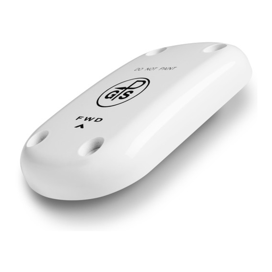
Summary of Contents for Garmin GA 35
- Page 1 190-00848-00 July 2014 Rev. F...
- Page 2 Garmin. Garmin hereby grants permission to download a single copy of these instructions and of any revision to these instructions onto a hard drive or other electronic storage medium...
- Page 3 Numbers Number Rewrote step 5 of antenna installation. Added table of hardware and torque specifications. Added caution pertaining to hardware use on GA 35 antennas. Appendix A Added caution about hardware use for GA 35 antennas. Appendix A Added note about hardware use for GA 36 antennas.
- Page 4 California to cause cancer, birth defects, or reproductive harm. This Notice is being provided in accordance with California’s Proposition 65. If you have any questions or would like additional information, please refer to our website at www.garmin.com. GA 35, GA 36, and GA 37 Antenna Installation Instructions...
-
Page 5: Table Of Contents
Figure A-1. GA 35 Antenna Installation Drawing ................... A-1 Figure A-2. GA 36 Antenna Installation Drawing ................... A-2 Figure A-3. GA 37 Antenna Installation Drawing ................... A-3 Page ii GA 35, GA 36, and GA 37 Antenna Installation Instructions Rev. F 190-00848-00... -
Page 6: General Description
Introduction This document provides installation instructions for the GA 35, GA 36, and GA 37 antennas. It is intended for use by persons certified by the Federal Aviation Administration (FAA) to install avionics equipment. These instructions apply to the GA 35, GA 36, and GA 37 antennas listed in the following table. Refer to the applicable Aero Antenna installation drawing listed in Table 1-1 for technical specifications for the antenna being installed. -
Page 7: Environmental Qualifications
Environmental Qualifications It is the responsibility of the installing agency to obtain the latest revisions of the GA 35, GA 36, and GA 37 Environmental Qualifications. The Environmental Categories are available on the Aero Antenna Drawing. To obtain a copy of these drawings, see the ‘Dealer Resource Center’ portion of the Garmin website, www.garmin.com. -
Page 8: Installation
2. The GPS antenna should be mounted in a location to minimize the effects of airframe shadowing during typical maneuvers. Typically mounting farther away from the tail section reduces signal blockage seen by the GPS antenna. GA 35, GA 36, and GA 37 Antenna Installation Instructions Page 2-1 190-00848-00... - Page 9 (ex. GPS and SiriusXM) provided the combination antenna is TSO authorized and has been tested to meet Garmin’s minimum performance standards. 3b. The GPS antenna should be mounted no closer than two feet from any antennas emitting more than 25 watts of power.
- Page 10 Figure 2-1. GPS Antenna Installation Considerations GA 35, GA 36, and GA 37 Antenna Installation Instructions Page 2-3 190-00848-00 Revision A...
-
Page 11: Siriusxm Antennas
FAA approved installation design and substantiating data. Antenna doublers are available from Garmin if installing the antenna using AML STC SA02018SE-D. Refer to the ‘Dealer Resource Center’ portion of the Garmin website, www.garmin.com, to obtain a copy of STC SA02018SE-D. Page 2-4 GA 35, GA 36, and GA 37 Antenna Installation Instructions Rev. -
Page 12: Antenna Grounding
2. Measure the resistance between the antenna connector body and a nearby exposed portion of conductive aircraft structure (e.g. a nearby exposed rivet on fuselage stringer). 3. The measured resistance should be equal to or less than 2.5 milliohms. GA 35, GA 36, and GA 37 Antenna Installation Instructions Page 2-5 190-00848-00... -
Page 13: Antenna Installation
10-32 Stainless Steel GA 37 CAUTION GA 35 serial numbers below 110000 required screws with 80 degree countersink angle and most aviation fasteners (AN509) are NOT compatible. Serial numbers 110000 and higher, AN509 hardware is compatible. Antennas installed with incompatible hardware or screws that have been over tightened will void antenna warranty. -
Page 14: Figure A-1. Ga 35 Antenna Installation Drawing
Appendix A INSTALLATION DRAWINGS Figure A-1. GA 35 Antenna Installation Drawing GA 35, GA 36, and GA 37 Antenna Installation Instructions Page A-1 190-00848-00 Rev. F... -
Page 15: Figure A-2. Ga 36 Antenna Installation Drawing
Figure A-2. GA 36 Antenna Installation Drawing Page A-2 GA 35, GA 36, and GA 37 Antenna Installation Instructions Rev. F 190-00848-00... -
Page 16: Figure A-3. Ga 37 Antenna Installation Drawing
Figure A-3. GA 37 Antenna Installation Drawing GA 35, GA 36, and GA 37 Antenna Installation Instructions Page A-3 190-00848-00 Rev. F...


Need help?
Do you have a question about the GA 35 and is the answer not in the manual?
Questions and answers