
Summary of Contents for GreenPower IET FORMULA GOBLIN G2
- Page 1 Global Partner National Partner National Partner National Partner Official Tools Provider Global Technology Partner Legal Partner Education ®...
-
Page 2: Table Of Contents
CONTENTS TOOLS REQUIRED FOR THE BUILD Introduction To Your Goblin G2 Kit Car • Metric Spanners (selection including 8,10,13, 17 and 19mm) • Metric Allen Keys (selection) Important Health & Safety Notes • Hammer Chassis Assembly • Safety Equipment • Tyre Pump with Pressure Gauge Chassis Assembly •... -
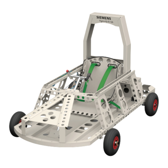
Page 3: Introduction To Your Goblin G2 Kit Car
INTRODUCTION TO YOUR GOBLIN G2 KIT CAR • Welcome to your Goblin G2. We hope you enjoy the Greenpower experience! • The key objective of building a Goblin is to encourage an appreciation and understanding of engineering and technology by the pupils involved. We recommend you involve a local engineer during the build to advise on technical matters and to act as a team mentor. • If you have a large number of pupils involved, we suggest you divide them into a number of teams to work on different areas of the build such as Chassis Team, Front Axle Team, Steering Team, Rear Axle Team, Wiring Team and Bodywork Team. Each team can then operate separately from the others coming together for the final assembly. • The method of assembly is basically clean and hence the project can safely take place in a classroom. Be aware that some parts may be covered in a light film of oil to prevent corrosion. It is advisable to use gloves when handling these parts. • Remember that the completed car will need to be stored somewhere dry and batteries, after use, should be recharged and stored fully charged to maintain performance. • Please ensure that pupils are carefully introduced to the tools used and that they use the correct tools for the various jobs. •... -
Page 4: Important Health & Safety Notes
IMPORTANT HEALTH & SAFETY NOTES • Although Goblin kits are designed to be built by 9-11 year olds there are still some potential risks when working with tools and electricity. Batteries • The batteries are absorbed glass mat (AGM) type batteries, so cannot leak or spill making them safer than other lead acid type batteries. • Caution must be taken when the batteries are out of their packing boxes as the terminals are exposed. We recommend that batteries are stored in their packing boxes when not in use in the car. Any shorting between battery terminals can be dangerous and damage the battery. • Before first charging batteries check your charger voltage. A 12v charger will charge a single battery at a time. A 24v charger must only be used to charge a pair of batteries linked in series. -
Page 5: Chassis Assembly
CHASSIS ASSEMBLY Tools Tip: Ordinary spanners Finger Tight: When you first GP1335 are good but, you can save fix nuts & bolts, don’t fully time by using a spanner tighten them. Do them up just on one end of a nut and with fingers to “finger tight”. bolt and a socket & ratchet Once a set of parts have been GP1334 handle on the other. See assembled and aligned then Finger Tight note. go round and fully tighten them. GP1333 GP1334 GP1233 Nyloc Nuts: Many nuts such as GP1227 used on the Goblin GP1230 GP1332 are Nyloc nuts. These have a plastic ring inserted in one end GP1227 which prevents then vibrating undone. They must be fitted with the plastic insert facing away from the head of the bolt. -
Page 6: Chassis Assembly
CHASSIS ASSEMBLY Small Parts: When you have a set of GP1233 small parts such as nuts & bolts to GP1230 work with place them in a plastic tray before use. This way you should avoid GP1336R losing them. Make sure you know which part is which though. GP1233 GP1230 GP1436 GP1233 GP1336L GP1230 GP1233 GP1436 GP1230 GP1230 GP1227 GP1391 GP1362 GP1338 GP1233 GP1362 GP1230 GP1212 GP1339 GP1337 GP1363 GP1216... -
Page 7: Steering Column Assembly
STEERING COLUMN ASSEMBLY Steering Column: Loosely assemble Smooth Steering: Once complete the steering should turn freely with no free play in it. the steering column & support Tightening or loosening the bolts on the support blocks and at the bottom can alter the blocks (GP1158) to the chassis. resistance. A small drop of oil or lubricant between the column and support blocks can Then connect the bottom section help. to the chassis using GP1237, 2 x GP1392 GP1236, GP1231 and GP1230. GP1237 should be done up until it stops the steering from turning and GP1216 then backed off just enough to allow GP1158 free movement. GP1231 should then GP1356 be tightened up to the bottom of the column to lock the bolt in place. GP1158 GP1216 GP1354 GP1215 GP1157 GP1393 GP1269 GP1230 GP1230 GP1231 GP1236 GP1157 GP1231 Steering Alignment: Once the wheels are fitted make sure that when the steering GP1269 GP1227... -
Page 8: Front Axle Assembly
FRONT AXLE ASSEMBLY Linch Pins: Be careful Caution: The bearings inside when fitting the linch pins the wheels will be greasy. This (GP1190) as they will spring lubrication reduces friction helping shut. Mind fingers! speed up your Goblin. Be sure to GP1358 use the correct wheel. The one GP1216 without bearings should be fitted to GP1360 the left rear. GP1207 GP1127 Safe Steering: Tighten the large nut & bolts (GP1202/ GP1190 GP1207) until there is no GP1204 movement up/down but it GP1001 can still turn from side to GP1142 side easily, Some lubrication is useful here. GP1201 GP1237 GP1216 Go Faster: To GP1215 reduce friction apply a little grease... -
Page 9: Rear Axle Assembly
REAR AXLE ASSEMBLY LEFT Keep it Tight: Where Nyloc nuts are not used, for example GP1002 and GP1005 a little medium GP1341 strength liquid thread lock can be used. This stops things vibrating loose. Search YouTube for tutorials. GP1365 GP1150 GP1291 GP1364 2 x GP1005 Drive Wheel: Your Goblin uses just one drive wheel on the left rear of the car. Power from the motor is Note: Grub screws, transferred to the wheel via GP1005, packaged inside GP1161 GP1138 GP1128 the roll pin, GP1004. So is GP1161, must be fully braking force - too much tightened to clamp bush hard braking risks wearing to axle. Third hole is NOT out the tyre. -
Page 10: Rear Axle Assembly
REAR AXLE ASSEMBLY RIGHT 1, 2, 3... Follow the notes in 3. Slide the centre part of numbered order. Roll pins the bearing, GP1128, onto should be inserted until GP1365 the axle. Do not tighten the GP1127 equal lengths show each grub screws until the axle is side of the axle. aligned on the car - but don’t GP1205 GP1364 forget to do so. GP1206 GP1342 GP1203 GP1001 GP1294 GP1128 GP1006 GP1128 1. Fit the disc hub, GP1381, GP1004 over the axle and secure in GP1128 place with a roll pin through GP1381 the hole nearest the centre GP1364 of the axle. -
Page 11: Brake And Throttle
BRAKE AND THROTTLE ASSEMBLY Brake Disc: The brake caliper straddles the disc. Having left the axle bearing grub screws loose once the caliper has been fitted and aligned these can be tightened. Further caliper alignment can be achieved by slightly loosening the black caliper bracket bolts, then whilst applying the brake, re- GP1040 tightening them. Aim to be able to spin the wheels without the disc rubbing on the brake pads in the caliper. GP1217 GP1216 GP1040 GP1131 GP1295 GP1355 GP1261 Friction: If your brake pads and disc are rubbing without the brake lever being pulled this will slow you down. -
Page 12: Motor Cage And Electrics
MOTOR CAGE AND ELECTRICS Safety Note: The red isolator switch key should be out of Note: Fit GP1034 and the switch except when about to drive. This immobilises associated cables before the Goblin by turning off all power. It should only be fitting GP1343 to chassis. inserted and switch to the on position immediately before GP1054 Ensure correct orientation driving with the driver in the car. so the red key aligns with GP1212 the off/on markings. GP1216 GP1219 GP1219 GP1216 GP1216 GP1215 GP1343 GP1264 GP1140 GP1383 GP1215 GP1123 GP1214 GP1216 GP1215 GP1216 GP1034 GP1264 GP1034 GP1216 GP1219... -
Page 13: Motor Assembly
MOTOR ASSEMBLY Motor Pulley: The pulley, GP1137, should be slid GP1237 onto the motor shaft. Moving it in or out along with adjustment of the axle pulley, GP1139 (see “REAR GP1230 AXLE ASSEMBLY LEFT” page), allows the two pulleys to be aligned. If the motor pulley is a tight fit use a softer GP1344 material such as a piece of wood or rubber mallet to tap it on. Tightening: Once the motor and axle pulleys have been aligned on the car the grub screw, GP1211, can be tightened. A little thread lock on this screw will prevent it coming undone. GP1230 GP1230 GP1227 GP1227 GP1211 GP1137 GP1248 Belt Tension: Correct drive belt tension is important to aid a quick start and prevent excess belt wear. Loosen the 4 bolts GP1237 and nuts GP1227, slide the motor GP1291 mounting plate, GP1344, towards the back of the car to tension the belt then re-tighten the nuts & bolts. If when starting to drive the car a graunching sounds occurs then the belt is too loose. As a general guide a correctly tensioned belt when twisted by hand should rotate between 45° and 90°. -
Page 14: Battery Tray Assembly
BATTERY TRAY ASSEMBLY GP1233 GP1230 GP1233 GP1230 GP1345... -
Page 15: Fitting Motor Cage To Chassis
FITTING MOTOR CAGE TO CHASSIS Note: Remember to fit GP1343 Motor Cage front fixings, not shown. Use the same fixings as at the rear. GP1343 GP1363 GP1216 GP1233 GP1230 GP1363 GP1216 GP1230 GP1227 GP1230 GP1219 GP1227 GP1216... -
Page 16: Fitting Batteries
FITTING BATTERIES Safety Note: Only fit and connect batteries once all GP1363 wiring is installed and has GP1346 GP1216 been double checked. GP1363 GP1216 Battery Connections: Take care not to over-tighten the battery terminal bolts. -
Page 17: Seat Assembly
SEAT ASSEMBLY GP1350 GP1349 GP1391 GP1362 GP1351 GP1212 GP1348 GP1347... -
Page 18: Fitting Seat
FITTING SEAT GP1442 GP1360 GP1360 GP1215... -
Page 19: Fitting Roll Bar
FITTING ROLL BAR GP1352 GP1230 GP1227 GP1436 GP1233 GP1233 GP1230 GP1230 GP1436 GP1397 GP1230 GP1233 GP1230 GP1233... -
Page 20: Harness Assembly
HARNESS ASSEMBLY Safety Harness: When installing the safety harness keep the buckle done up to help prevent GP1365 twisting during fitting. GP1364 GP1120 GP1364 GP1192 GP1365 Note: The safety harness must be GP1364 adjusted to securely restrain the driver. A loose harness will mean GP1364 drivers will not be permitted to start GP1192 an event. It is the responsibility of teams to ensure suitable adjustments are made. -
Page 21: Wiring Installation
WIRING INSTALLATION Note: All wires for your Goblin G2 are labelled and must be connected following the diagram on the next page. Please take great care when installing the wiring to your car as incorrect installation may cause damage, or even fire to wires, motor and or batteries. -
Page 22: G2 Wiring Diagram
GOBLIN G2 WIRING DIAGRAM... -
Page 23: Battery Charging
BATTERY CHARGING Your Goblin G2 kit is not supplied as standard with a battery charger. If you need to purchase one please visit our online shop at Greenpower.co.uk where you will find a range of suitable chargers available. Do NOT connect charger to mains supply before proceeding. Batteries can be charged either singly using a 12 volt charger or as a pair using a 24 volt charger. Failure to correctly connect your battery charger may damage batteries and can be dangerous. Please CHECK your battery charger output voltage before proceeding and select step 1 or 2 below accordingly. -
Page 24: Rebuilds & Spare Parts
REBUILDS & SPARE PARTS Greenpower want you to be able to use your Goblin for many years to come. Each year your Goblin can be dismantled and rebuilt by a new team of pupils. To ensure you have everything necessary during your event season and when rebuilding your car, Greenpower can supply any necessary spare parts. These can be ordered online, by telephone or by email. Details below: www.greenpower.co.uk 01243 552305 info@greenpower.co.uk For teams outside the United Kingdom please contact your country specific licensed Greenpower agent. If your country doesn’t have a licensed agent please email: sales@greenpower.co.uk or call +44 1243 552 305. -
Page 25: Test Driving & Driver Training
TEST DRIVING & DRIVER TRAINING • Once your build is complete and the wiring has been double-checked try giving it a test drive! The bodywork does not need to be in place for testing. • Initial driver training should be undertaken with no power to the car. To familiarise drivers with the steering and brake controls push them around a slalom type course. • Once drivers are familiar with steering and braking they can conduct their first powered runs. These should take place on a hard surface with no obstructions. All spectators must be behind solid barriers. Goblins are not suitable for use on soft grass surfaces. • To limit speed on initial runs the car can be powered using a single battery. This will run the car on 12 volts rather than 24 volts and result in the car running at half speed. To do this connect wire G2C to the negative terminal and wire G2B to the positive terminal of the one battery. Wire G2A is then not used. • Driving should only be conducted with drivers wearing helmet, gloves, eye protection (visor or goggles), long sleeves and trousers. Long hair should be tucked into the helmet to prevent it being caught in any moving parts. Once the driver is comfortable and there is a clear open area, turn on the battery isolator switch at the rear of the car. The driver can then switch on the black rocker switch at the front of the car. If all is well, the red LED on this switch will then illuminate. Give the car a gentle push from behind using the roll over bar. As this is done, the driver can press the throttle button to drive off. • If a rasping noise is heard, especially when pulling away, the drive belt is loose and requires correct tensioning. Failure to correctly tension the belt will result in premature wear and failure. • The driver should now practise steering through a course laid out using cones or markers increasing their pace and switching to running on both batteries as they become more experienced. -
Page 26: Final Pre-Race Checks
FINAL PRE-RACE CHECKS To gain the best performance out of your Goblin is it important to reduce friction: • Ensure the brake is not binding/rubbing. If it is then adjust the pads and/or the caliper/axle position to ensure free running. Free running is best checked with the wheels off the ground. • Tyre pressures – check all tyres are inflated to the maximum pressure recommended as marked on the tyres. • Wheel bearings – Ensure the bearing wheels are greased to ensure they spin freely. This doesn’t apply to the left rear driven wheel. • Front wheel alignment – the front wheels should run parallel to each other. Excessive toe in or out will reduce performance. • Steering – check that the steering can be turned smoothly without binding or excess slack. This is best done with the front wheels off the ground. • Brake performance and adjustment – pulling on the brake lever should lock the rear axle such that the car cannot be pulled along with driver on board without the rear wheels skidding. If this is not the case then adjust immediately. • Fasteners – check all nuts and bolts are secure and tight. Loose fasteners will result in failing event scrutineering. • Batteries – to maintain the best performance from your batteries they should never be left discharged. See the page on Battery Charging for further advice. • Electrical Faults – Incorrect wiring installation can result in either of the two fuses blowing. If this has happened there is a fault which needs to be corrected before proceeding. Please be very careful as whilst the fuses are there as a safety measure incorrect wiring can in the worst case result in fire! - Page 27 MORE INFORMATION If you’d like more information please contact: /GreenpowerRacing Greenpower Education Trust /Greenpowertrust The Greenpower Centre Arundel Road, Fontwell, West Sussex BN18 0SD /Greenpowertrust T: 01243 552 305 E: info@greenpower.co.uk /company/greenpower-education-trust Greenpower Education Trust is a charity registered in England and Wales no. 1133536 and in Scotland no. SC046969 www.greenpower.co.uk © All Rights Reserved - Greenpower Education Trust...
Need help?
Do you have a question about the IET FORMULA GOBLIN G2 and is the answer not in the manual?
Questions and answers