Table of Contents
Advertisement
ALPHACALL MF
Installation & operations manual
The information in this manual is subject to change
without further notice. No rights can be derived from
this manual.
Document
:
ALPHACALL MF Manual
Revision
:
1.0
© ALPHATRON MARINE B.V.
ALPHATRON MARINE B.V.
Schaardijk 23
3063 NH ROTTERDAM
The Netherlands
Tel: +31 (0)10 – 453 4000
Fax: +31 (0)10 – 452 9214
P.O. Box 210003
3001 AA ROTTERDAM
Web: www.alphatronmarine.com
Mail:
info@alphatronmarine.com
Advertisement
Table of Contents

Subscribe to Our Youtube Channel
Summary of Contents for Alphatron ALPHACALL MF
- Page 1 The information in this manual is subject to change Fax: +31 (0)10 – 452 9214 without further notice. No rights can be derived from this manual. P.O. Box 210003 3001 AA ROTTERDAM Document ALPHACALL MF Manual Revision Web: www.alphatronmarine.com © ALPHATRON MARINE B.V. Mail: info@alphatronmarine.com...
-
Page 2: Table Of Contents
Switching the ALPHACALL MF on/off ............15 4.1.2 Dimming the ALPHACALL MF ............... 15 4.1.3 Setting the ALPHACALL MF outgoing and incoming volume ......15 4.1.4 (De)selecting the substations ................. 15 4.1.5 Answering a call from one of the substations ..........16 4.1.6... - Page 3 Nothing from this manual may be copied and/or published by means of print, photocopy, microfilm or in whatever form whatsoever, without the prior written permission of Alphatron. Although this manual has been created with the greatest possible care, Alphatron does not accept any liability for the consequences of any inaccuracies it contains.
-
Page 4: Version Control
ALPHACALL MF VERSION CONTROL Revision number Description Date V1.0 document drawn up 03/06/08 ALPHACALL MF manual version 1.0 Page 4 of 22... -
Page 5: Introduction
INTRODUCTION The ALPHACALL MF is one of the products from the ALPHALINE MF product line. Because the ALPHACALL MF allows the connection of up to 10 substations, it can be used on many different types of ship. When designing the ALPHACALL MF, careful attention was paid to the production of sound that is as crisp and clear as possible. -
Page 6: Installation
ALPHACALL MF INSTALLATION Materials supplied The ALPHACALL MF hardware consists of the following parts: Mounting frame ALPHACALL MF main unit 10x Substation connector 1x Mic, PTT, speaker connector 1x External call connector 1x Power connector Figure 1: The complete hardware of the ALPHACALL MF ALPHACALL MF manual version 1.0... -
Page 7: Installing The Alphacall Mf
ALPHACALL MF Installing the ALPHACALL MF The ALPHACALL MF can be installed in a number of different ways. The instrument can be flush mounted and there is also a surface mounting option. 3.2.1 Flush mounting the ALPHACALL MF De ALPHACALL MF can be installed horizontally, vertically as well as at an angle. The possible positions are shown in Figure 2. - Page 8 The mounting frame must be attached using four screws through the intended holes. These holes are indicated with arrows in Figure 3. After the mounting frame has been installed, the ALPHACALL MF can be pressed into it. The instrument will be kept in position by a click/spring system.
-
Page 9: Alphacall Mf Surface Mounted
ALPHACALL MF 3.2.2 ALPHACALL MF surface mounted For surface mounting the ALPHACALL MF, an additional DIN 144 housing is required. This housing is not supplied as standard. Figure 4: Surface mounted housing MF line ALPHACALL MF manual version 1.0 Page 9 of 22... -
Page 10: Connecting The Alphacall Mf
ALPHACALL MF Connecting the ALPHACALL MF The ALPHACALL MF has in total 13 connectors at the back of the instrument. The various connectors and their functions are given below. Connector 1 = power supply (24VDC) Connector 2 = Ext. speaker, microphone and foot switch... -
Page 11: Terminating The Cables
ALPHACALL MF 3.3.1 Terminating the cables The ALPHACALL MF must be connected in accordance with the instructions in the Appendix. When designing the ALPHACALL MF, careful attention has been given to the sound quality. To guarantee this quality in the installed system, here are some recommendations regarding the grounding of the system: Prevent ground loops, make one central ground point. -
Page 12: Connecting The Power Supply
ALPHACALL MF 3.3.2 Connecting the power supply The ALPHACALL MF must be connected to a 22VDC to 32VDC power supply that can supply at least 2 ampere. Connector 1 in Figure 6 is the power connector. The polarity of the power connectors is shown on the sticker on the back of the instrument. -
Page 13: Connecting The Substations
ALPHACALL MF 3.3.4 Connecting the substations Up to 10 substations can be connected to the ALPHACALL MF. The outputs for substations 7 through 10 have the option of generating an external signal at the substation, for instance, a flashing light, see the relevant section of this document. The intercom must be connected to the substation using a three-core cable. -
Page 14: Connecting The External Signalling Device
The outputs for the substations 7 through 10 have the option of generating an external signal at the substation for instance by means of a flashing light. The output signal of these connections is 12V and max. 10mA. The complete connection diagram of the ALPHACALL MF is included in the Appendix of this manual. -
Page 15: Operating The Alphacall Mf
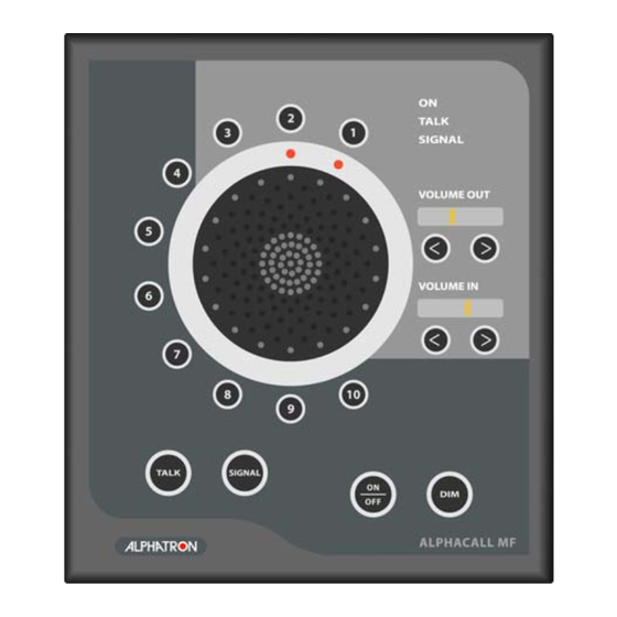
4.1.2 Dimming the ALPHACALL MF To change the backlight of the ALPHACALL MF, the ‘dim’ button must be pressed briefly and repeatedly. The lighting will change in a cycle from minimum to maximum. 4.1.3 Setting the ALPHACALL MF outgoing and incoming volume Use the ‘<’... -
Page 16: Answering A Call From One Of The Substations
On the back of the instrument, there are three dip switches that can be used to set the colour of the backlight of the buttons. The text above the switches corresponds to the following colours: W=white, G=green and R=red. Figure 8: Setting the backlight colour ALPHACALL MF manual version 1.0 Page 16 of 22... -
Page 17: Troubleshooting
Value Comments Operating temperature 0°C to +50°C Storage temperature -10°C to +50°C TECHNICAL SUPPORT If you require technical support for this ALPHACALL MF, please contact: Alphatron Marine BV Schaardijk 23 3063NH, Rotterdam P.O. Box 21003 The Netherlands Tel: 0031(0)10 4534000 Fax: 0031(0)10 4529214 www.alphatronmarine.com... -
Page 18: Alphatron Dealers (Authorized)
UNITED ARAB EMIRATES Elcome International L.L.C. Al Jadaf Dockyard – DY159 P.O. Box 1788 DUBAI UNITED ARAB EMIRATES Tel. + 971 4 4049100 Fax. + 971 4 049200 Internet: www.elcome.ae E-mail: info@elcome.ae ALPHACALL MF manual version 1.0 Page 18 of 22... -
Page 19: Appendix 1: Mounting Frame
ALPHACALL MF Appendix 1: Mounting frame ALPHACALL MF manual version 1.0 Page 19 of 22... -
Page 20: Appendix 2: Instrument Dimensions
ALPHACALL MF 10 Appendix 2: Instrument dimensions ALPHACALL MF manual version 1.0 Page 20 of 22... -
Page 21: Appendix 3: Complete Connection Diagram
ALPHACALL MF Appendix 3: Complete connection diagram ALPHACALL MF manual version 1.0 Page 21 of 22... -
Page 22: Notes
ALPHACALL MF 11 NOTES: ALPHACALL MF manual version 1.0 Page 22 of 22...
Need help?
Do you have a question about the ALPHACALL MF and is the answer not in the manual?
Questions and answers