Table of Contents
Advertisement
Quick Links
®
This installation manual provides information for installing
and configuring the Loren Cook Company constant pressure
control system. The system requires a Loren Cook Company
fan with an Electronically Commutated, EC, motor with exter-
nal speed control capability. The manual does not cover any
other installation details or applications.
Carefully read this publication and any sup-
plemental documents prior to any installation
or maintenance procedure.
For additional safety information, refer to AMCA publication
410-96, Safety Practices for Users and Installers of Industrial
and Commercial Fans. This document and all Cook publica-
tions may be obtained from Cook by phoning (417) 869-6474,
extension 166; by FAX at (417) 832-9431; or by e-mail at
info@LorenCook.com. All Cook publications are available on
LorenCook.com.
For information and instructions on special equipment, con-
tact Cook at (417) 869-6474.
Location and Maintenance
Consider the following points while choosing a location for the
Vari-Flow Pressure Controller.
• Install the controller indoors.
• Do not place the controller on the floor.
• Maintain a temperature between 0°C to 40°C (32°F to
104°F). A temperature beyond this range may cause con-
densation and sweating of metal parts.
• Maintain a low humidity, dry, and clean atmosphere. En-
sure that the controller is not in the path of blowing dust,
rain, or snow.
Follow these guidelines prior to installation.
• Clean the components to remove any deposit of dirt,
water, ice, or snow and wipe them dry.
• Dry components using a portable electric heater to
remove any buildup of moisture.
• Allow the cold metal parts to reach room temperature to
avoid sweating.
Installation Warning
Install the Pressure Controller indoors only to avoid additional risks.
Voltage Warning
Low-voltage control wires and line voltage power wires must not be
installed in same conduit. Failure to follow these instructions could
result in malfunction or damage.
Disconnect Warning
ALWAYS disconnect power prior to working on fan. Failure to
comply with these safety precautions could result in property
damage, serious injury, or death.
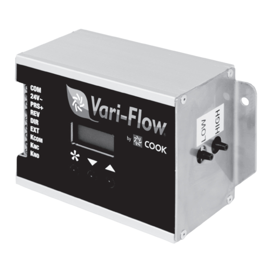
VARI-FLOW PRESSURE CONTROLLER IO&M
Vari-Flow Pressure Controller
Specification and Installation Instructions
Installation
The following steps and components are important to the
proper operation of the Pressure Controller.
Pressure Tap
Pressure taps are used to connect the controller to the
environment being measured. Use pressure taps by placing
them in the respective duct or room that needs control. Fol-
low these guidelines while mounting the pressure taps.
• Ensure that there are no kinks along the length of the
pressure tube.
• Do not pinch the pressure tube.
• Form a drip loop in the tubing as it enters the pressure
controller. This avoids condensation build up inside the
pressure tube and damages to the controller's sensor.
• Drip loop should be at least 1" (25 mm) greater than high-
est measured pressure (as measured in inches, w.c.)
factoring in error conditions in the system. (Example: If
static pressure is being measured in 4" w.c., then the
bottom of drip loop should be 5" or more below the high
pressure port.)
Low Pressure Port
High Pressure Port
Duct
Drip Loop
B51004-002
Advertisement
Table of Contents

Subscribe to Our Youtube Channel
Summary of Contents for Loren Cook Vari-Flow
- Page 1 Loren Cook Company constant pressure The following steps and components are important to the control system. The system requires a Loren Cook Company proper operation of the Pressure Controller. fan with an Electronically Commutated, EC, motor with exter- nal speed control capability.
- Page 2 • Do not mount the pressure tap in an enclosed area such Open to Atmosphere 24V~ as a closet and areas that are prone to drafts. Low Pressure Port Prs+ 1/8" (3.175mm) Tubing Kcom High Pressure Port To Pressure Tap VARI-FLOW PRESSURE CONTROLLER IO&M B51004-002...
- Page 3 Use the arrow keys to change the value of the current menu item. Press and hold an arrow key to scroll rapidly through the values. Changes are automatically saved. The Vari-Flow Pressure Controller automatically exits the menu after 20 seconds of inactivity.
- Page 4 To make a warranty claim, notify Loren Cook Company, General Offices, 2015 East Dale Street, Springfield, Missouri 65803-4637, explaining in writing, in detail, your complaint and referring to the specific model and serial numbers of your fan. Upon receipt by Loren Cook Company of your written complaint, you will be notified, within thirty (30) days of our receipt of your complaint, in writing, as to the manner in which your claim will be handled.
Need help?
Do you have a question about the Vari-Flow and is the answer not in the manual?
Questions and answers