Table of Contents
Advertisement
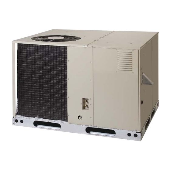
R6GD SERIES
USER's MANUAL & INSTALLATION INSTRUCTIONS
Single Package Gas Heating / Electric Cooling - 3 Phase
Premium Model Shown
FIRE OR EXPLOSION HAZARD
• Failure to follow safety warnings exactly
could result in serious injury or property
damage.
• Installation and service must be performed
by a qualifi ed installer, service agency or the
gas supplier.
• Do not store or use gasoline or other
fl ammable vapors and liquids in the vicinity
of this or any other appliance.
DO NOT DESTROY. PLEASE READ CAREFULLY AND KEEP IN A SAFE PLACE FOR FUTURE REFERENCE.
It is your responsibility to know this product better than your customer. This includes being able to install the product according
to strict safety guidelines and instructing the customer on how to operate and maintain the equipment for the life of the product.
Safety should always be the deciding factor when installing this product and using common sense plays an important role as
well. Pay attention to all safety warnings and any other special notes highlighted in the manual. Improper installation of the unit
or failure to follow safety warnings could result in serious injury, death, or property damage. These instructions are primarily
intended to assist qualifi ed individuals experienced in the proper installation of this appliance. Some local codes require
licensed installation/service personnel for this type of equipment. After completing the installation, return these instructions to
the customer's package for future reference.
!
WARNING:
• Do not try to light any appliance.
• Do not touch any electrical switch; do not
use any phone in your building.
• Leave the building immediately.
• Immediately call your gas supplier from a
neighbors phone. Follow the gas suppliers
instructions.
• If you cannot reach your gas supplier, call
the fi re department.
ATTENTION INSTALLERS:
WHAT TO DO IF YOU SMELL GAS
13 SEER
Advertisement
Table of Contents

Summary of Contents for Mammoth R6GD Series
- Page 1 R6GD SERIES 13 SEER USER’s MANUAL & INSTALLATION INSTRUCTIONS Single Package Gas Heating / Electric Cooling - 3 Phase Premium Model Shown WARNING: FIRE OR EXPLOSION HAZARD WHAT TO DO IF YOU SMELL GAS • Failure to follow safety warnings exactly •...
- Page 2 USER INFORMATION Important Safety Information ........4 WARRANTY INFORMATION Operating Instructions ..........4 A warranty certifi cate with full details is included with the Cooling Operation .............4 Air Conditioner. Carefully review these responsibilities with Heating Operation .............4 your dealer or service company. The manufacturer will not Turning the Air Conditioner Off ........4 be responsible for any costs found necessary to correct Operating the Indoor Blower Continuously ....4...
-
Page 3: Table Of Contents
INSTALLER INFORMATION STARTUP & ADJUSTMENTS ........18 IMPORTANT SAFETY INFORMATION .......5 Pre - Start Checklist ..........18 REQUIREMENTS & CODES ........6 Start-up Procedure ..........18 GENERAL INFORMATION ..........7 Air Circulation ............18 Before You Install this Unit .........7 System Cooling ............18 Locating the Equipment..........7 System Heating ............18 Heating Load ............7 Verifying &... - Page 4 USER INFORMATION IMPORTANT SAFETY INFORMATION Turning the Unit OFF Change the thermostat’s system mode to OFF and the fan Safety markings are used frequently throughout this mode to AUTO (See Figure 1). NOTE: The system will not manual to designate a degree or level of seriousness and operate, regardless of the temperature selector setting.
-
Page 5: Important Safety Information
INSTALLER INFORMATION IMPORTANT SAFETY INFORMATION WARNING: Please read all instructions before servicing this equipment. Do not place combustible material on or against Pay attention to all safety warnings and any other special the unit cabinet. Do not place combustible notes highlighted in the manual. Safety markings are materials, including gasoline and any other used frequently throughout this manual to designate a fl... -
Page 6: Requirements & Codes
• This equipment contains liquid and gaseous refrigerant REQUIREMENTS AND CODES under high pressure. Installation or servicing should only This unit must be installed in accordance with be performed by qualifi ed trained personnel thoroughly instructions outlined in this manual, all applicable familiar with this type equipment. -
Page 7: General Information
GENERAL INFORMATION maintained in order to achieve rated performance. See Figure 2 for minimum clearances to obstructions. The R6GD Single Package Gas Heating / Electric Cooling • A clearance of at least 36 inches from the blower access Unit is designed only for outdoor rooftop or ground level panel and from the louvered control access panel is installations and can be readily connected to the high recommended for servicing and maintenance. -
Page 8: Venting Requirements
• The requirements in Canada (B149.1) are structured A vent cover assembly has been supplied with the unit. differently. Consult with B149.1 and local code offi cials and can be found secured to the gas controls within the for Canadian installations. control area of this unit. - Page 9 AVERTISSEMENT: WARNING: RISQUE D’EMPOISONNEMENT AU CARBON MONOXIDE POISONING HAZARD MONOXYDE DE CARBONED Failure to follow the steps outlined below Le non-respect des consignes suivantes portant for each appliance connected to the venting sur chacun des appareils raccordés au système system being placed into operation could result d’évacuation mis en service pourrait entraîner in carbon monoxide poisoning or death.
-
Page 10: Circulating Air Supply
Circulating Air Supply • If outside air is utilized as return air to the unit for ventilation or to improve indoor air quality, the system must be designed so that the return air to the unit is WARNING: not less than 50° F (10° C) during heating operation. Products of combustion must not be allowed to •... -
Page 11: Acoustical Duct Work
Acoustical Duct Work • Suffi cient clearance for unobstructed airfl ow through Certain installations may require the use of acoustical the outdoor coil must also be maintained in order to lining inside the supply duct work. achieve rated performance. See page 7 for information •... -
Page 12: Removal Of Internal Filter Rack
Removal of Internal Filter Rack (3 Phase Only) 1. Remove the return air panel from the unit. 2. Remove the height adjustment screw from the inside of the rack. 3. Remove (1) screw securing the assembly to the coil located on the left leg of the rack. NOTE: The assembly can now be easily collapsed and removed from the unit. -
Page 13: Electrical Wiring
ELECTRICAL WIRING be capable of electrically de-energizing the outdoor unit. See unit data label for proper incoming fi eld wiring. Any other wiring methods must be acceptable to authority WARNING: having jurisdiction. To avoid risk of electrical shock, personal injury, •... -
Page 14: Grounding
Thermostat / Low Voltage Connections COPPER WIRE SIZE — AWG • The R6GD unit is designed to operate from a 24 VAC (1% Voltage Drop) Class II control circuit. The control circuit wiring must Supply Wire Length-Feet Supply Circuit comply with the current provisions of the NEC (ANSI/ Ampacity NFPA 70) and with applicable local codes having jurisdiction. -
Page 15: Checking Heat Anticipator Settings
• The thermostat should be mounted about 5 feet above the Unbalanced 3-Phase Supply Voltage fl oor on an inside wall. DO NOT install the thermostat on Voltage unbalance occurs when the voltages of all phases an outside wall or any other location where its operation of a 3-phase power supply are no longer equal. -
Page 16: Optional Humidistat
Optional Humidistat GAS SUPPLY AND PIPING An optional humidistat may be installed in the return • All gas piping must be installed in compliance with air duct for humidity control (when needed), maximum local codes and utility regulations. In the absence system capacity and energy effi... -
Page 17: Leak Check
This unit only has right side gas entry. When connecting changes required depend on the installation altitude and the gas, provide clearance between the gas supply line the heating value of the gas (based on sea level) which and the entry hole in the unit’s casing to avoid unwanted can be obtained from your local gas utility. -
Page 18: Startup & Adjustments
START UP AND ADJUSTMENTS System Cooling 1. Set the thermostat’s system mode to COOL and the Pre-Start Check List fan mode to AUTO. Gradually lower the thermostat Verify the unit is level and allows condensate to drain. temperature setpoint below room temperature and verify ... -
Page 19: Verifying & Adjusting Firing Rate
The integrated control starts the circulating air blower 30 3. Remove the close-off plate immediately after the over- seconds after the gas valve is opened. The control is factory temperature limit control opens. If the unit operates wired to turn the blower motor off 135 seconds after the for more than four minutes with no return air, set the gas valve is closed. -
Page 20: Manifold Pressure Adjustment
them to the service ports on the unit. Refrigerant charging OPERATING SEQUENCE must be done by qualifi ed personnel familiar with safe The operating sequences for the heating, cooling, and and environmentally responsible refrigerant handling fan modes are described below. Refer to the fi eld and procedures. -
Page 21: Cooling Mode
8. After the gas valve opens (30 seconds), the blower will EQUIPMENT MAINTENANCE ramp to the selected airfl ow and continues to run. 9. When the thermostat has been satisfi ed, the W terminal WARNING: on the integrated control is de-energized. To avoid risk of electrical shock, personal injury, 10. -
Page 22: Cleaning Of Heat Exchanger
• The motors for the circulating air blower, outdoor fan, speed reversible drill. Slowly insert and rotate the cable and combustion blower are pre-lubricated at the factory. into the top portion of the heat exchanger. Operate the No further oiling is required for the life of this product. drill alternating between forward and reverse, working •... -
Page 23: Component Functions
COMPONENT FUNCTIONS REPLACEMENT PARTS Replacement parts are available through all Nordyne Flame Roll-Out Control distributors. Please have the complete model and serial The fl ame roll-out control acts to verify that the burner number of the unit when ordering replacement parts. fl... -
Page 24: Figures & Tables
FIGURES & TABLES 24 9/10 3/4" NPT Female Drain Connector DOWNFLOW SUPPLY DUCT OPENING 47 1/2 13 1/2 13 1/2 13 3/10 23 1/2 DOWNFLOW RETURN DUCT OPENING Electric Top View Supply Entry Low Voltage Entry Gas Supply 29.75 Entry 23.75 15.75 47.5... -
Page 25: Airflow Information
AIRFLOW INFORMATION Table 10. Nominal Airfl ow Rates and Temperature Rises ( °... -
Page 26: Gas Information
GAS INFORMATION CAPACITY OF BLACK IRON GAS PIPE (CU. FT. PER HOUR) FOR NATURAL GAS (SPECIFIC GRAVITY - 0.60) NOMINAL BLACK LENGTH OF PIPE RUN (FT) IRON PIPE DIAMETER (IN.) 1 1/4 1,050 1 1/2 1,600 1,100 NOTES The cubic feet per hour listed above must be greater than the cubic feet per hour of gas fl ow required by the equipment. To determine the required cubic feet per hour of gas fl... - Page 27 FOR YOUR SAFETY READ BEFORE OPERATING POUR VOTRE SÉCURITÉ. À LIRE AVANT L’EMPLOI ATTENTION! L’inobservation de ces instructions peut WARNING: If you do not follow these instructions entraîner un incendie ou une explosion pouvant causer exactly, a fi re or explosion may result causing property des dam mages à...
-
Page 28: Electrical Information
Figure 12. Wiring Diagram for 208/230V / 3 Phase / 60 Hz Unit... - Page 29 WHITE GREEN YELLOW BLACK BLACK YELLOW Figure 13. Wiring Diagram for 460V / 3 Phase / 60 Hz Unit...
-
Page 30: R6Gd Charging Charts
R6GD CHARGING CHARTS R6GD-X36 Charging Chart - Cooling Remove refrigerant when above curve Add refrigerant when below curve Liquid Temperature (° F) Figure 14. Charging Chart for 3 Ton Units R6GD-X48 Charging Chart - Cooling Remove refrigerant when above curve Add refrigerant when below curve Liquid Temperature (°... - Page 31 R6GD CHARGING CHARTS - CONTINUED R6GD-X60 Charging Chart - Cooling Remove refrigerant when above curve Add refrigerant when below curve Liquid Temperature (° F) Figure 16. Charging Chart for 5 Ton Units...
-
Page 32: French Translations
FRENCH TRANSLATIONS AVERTISSEMENT: AVERTISSEMENT: RISQUE D’INCENDIE OU D’ EXPLOSION RISQUE DE CHOC ÉLECTRIQUE, D’INCENDIE • Le non-respect avertissements OU D’EXPLOSION sécurité pourrait entraîner des blessures Le non-respect des avertissements de sécurité graves, la mort ou des dommages matériels. pourrait entraîner un fonctionnement dangereux •... -
Page 36: Installation/Performance Checklist
INSTALLATION/PERFORMANCE CHECK LIST GAS SYSTEM: INSTALLATION ADDRESS: Natural Gas Type: (circle one) Propane CITY ________________________ STATE ________________ Gas pipe connections leak-tested? UNIT MODEL # ________________________________________ Gas Line Pressure: ____________________________ (in - W.C.) Is there adequate fresh air UNIT SERIAL # _______________________________________ supply for combustion and ventilation? Unit Installed Minimum clearances per...
Need help?
Do you have a question about the R6GD Series and is the answer not in the manual?
Questions and answers