Table of Contents
Advertisement
Hardware Installation Manual
Modular Silicon Expansion Valve (MSEV)
High Capacity Modular Silicon Expansion Valve (HC-MSEV)
Very High Capacity Modular Silicon Expansion Valve (VHC-MSEV)
Universal SuperHeat Controller/Sensor (USHX)
Revision 1.7
DunAn Microstaq, Inc.
4120 Freidrich Lane, Suite 225
Austin, Texas 78744 United States
(512) 628-2890
www.dmq-us.com
Published: July 2019
©2019
Advertisement
Table of Contents

Subscribe to Our Youtube Channel
Summary of Contents for DMQ A12V-U112
- Page 1 High Capacity Modular Silicon Expansion Valve (HC-MSEV) Very High Capacity Modular Silicon Expansion Valve (VHC-MSEV) Universal SuperHeat Controller/Sensor (USHX) Revision 1.7 DunAn Microstaq, Inc. 4120 Freidrich Lane, Suite 225 Austin, Texas 78744 United States (512) 628-2890 www.dmq-us.com Published: July 2019 ©2019...
- Page 2 This manual is applicable to the following MSEV model numbers: A12V-U112 A24V-U112 A12V-U116 A24V-U116 A12V-U118 A24V-U118 A12V-U120 A24V-U120 A12V-U124 A24V-U124 A12V-C112 A24V-C112 A12V-C116 A24V-C116 ...
-
Page 3: Table Of Contents
Table of Contents Before You Begin ........................1 About This Manual ........................1 Document Conventions ......................1 Acronyms ..........................1 About the MSEV Series and the USHX ..................2 Mechanical Installation ......................4 Installing a MSEV Series Valve ....................4 Installing the USHX ........................6 Electrical Wiring ........................ -
Page 4: Before You Begin
1 Before You Begin 1.1 About This Manual The following table shows a summary of the sections in this document and their descriptions. Table 1-1 Descriptions of the Sections in the Document Section Title Description Before You Begin This section provides preliminary information about the products. This section provides instructions about the mechanical installation Mechanical Installation of the MSEV series and the USHX in the system. -
Page 5: About The Msev Series And The Ushx
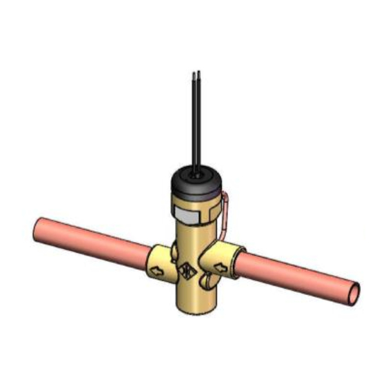
1.4 About the MSEV Series and the USHX The MSEV series valves Modular Silicon Expansion Valve (MSEV), High Capacity Modular Silicon Expansion Valve (HC-MSEV) and the Very High Capacity Modular Silicon Expansion Valve (VHC-MSEV), shown in Error! Reference source not found., are two-stage proportional control expansion valves that utilize DunAn Microstaq’s patented silQflo®... - Page 6 The USHX and its wiring harness pin assignments are shown in Table 1-4. Table 1-4 USHX and Wiring Harness Pin Assignments USHX-G1.3b Series Model Numbers USHC-G1.3b-BAAAXXX USHS-G1.3b-BAAAXXX Wiring Harness Model Pin Number Pin Name Pin Function Type of Wire WH-USHX-AX ...
-
Page 7: Mechanical Installation
2 Mechanical Installation This section describes the mechanical installation of a MSEV series valve and USHX. Figure 2-1 below shows an example of a typical system where the MSEV series valve and USHX devices would be integrated into. Like conventional thermostatic expansion valves (TXVs) or electronic expansion valves (EEVs), the MSEV series valve is installed at the inlet of the evaporator. - Page 8 Figure 2-1. It can be installed at about 6” away from the valve. The MSEV series valve must be protected against contaminants to ensure its optimal operation. DMQ highly recommends using a filter drier with a 20 micron filtration rating. The MSEV series valve installation process is now complete.
-
Page 9: Installing The Ushx
2.2 Installing the USHX To install the USHX, complete the following steps: Pump down and recover any residual refrigerant from the system. This may have already been done if a MSEV series valve was installed before this step. Obtain any ¼” access fitting that is compatible with the system. In this section, a ¼” access fitting with a 3/16”... - Page 10 Figure 2-5: Brazed access fitting Mount the USHX onto the access fitting. First, turn the USHX clockwise by hand until some resistance is observed. Then, use a torque wrench to tighten the USHX to 70 in-lb as shown in Figure 2-6. Figure 2-6 USHX Installation with Torque Wrench (70 in-lb) When torque wrench not available use 7/16”...
- Page 11 Install the thermistor at the outlet of the evaporator and close to the access fitting using a zip tie, as shown below in Figure 2-8. The thermistor should be located at either the 10 o’clock or 2 o’clock position only. Figure 2-8 Thermistor installation at evaporator outlet Ensure that the thermistor wire is not tied down to the tubing.
- Page 12 Refer to USHX Software User Interface Manual to set up communications between the USHX and the computer. Supply power to the USHX with a power supply and power it on. Ensure that the settings in the GUI meet the system requirements (i.e. double check the Refrigerant, Target Superheat, Device Mode, and other settings).
-
Page 13: Electrical Wiring
3 Electrical Wiring After the mechanical installation of the MSEV series valve(s) and/or USHX(s) into the system, complete the electrical wiring of the system by completing the following steps. Refer directly Section 3.2 to if more than one unit was installed. 3.1 Single USHC and MSEV Series Valve or Single USHS Do NOT turn the power source ON until all electrical wiring setup is complete. - Page 14 The reading should be at or near 12VDC, 24VDC, or 24VAC depending on the MSEV series valve and power source. When supplying 24V, the voltage must be within the range of 20.4V to 27.6V. When supplying 12V, the voltage must be within the range of 10.2V to 13.8V.
-
Page 15: Multiple Ushcs And Msev Series Valves Or Multiple Ushss
Connect the RS485 communication wires (2-wire gray cord that contains a red and a black wire and the green data ground wire) to the D+, D-, and SG terminals on the USB-to-RS485 converter as shown below in Figure 3-3. For the USHX setup, the RS485 will require an adapter with built-in electrical isolation. - Page 16 an over-voltage. If a 24V MSEV series valve is powered by a 12V power source, the valve will not fully open due to an under-voltage. Obtain a Class 2 24 VAC transformer with a capacity of 40 to 100 VA and an output of 24 VAC at a frequency of 60 Hz.
- Page 17 Install the transformer or power supply at the center of the all the USHXs. The below wiring methodology is recommended so that the load of the controllers on either end of the transformer will be the same. Figure 3-5 Multiple USHCs and MSEV series valves networking diagram The wiring schemes of the ‘Multiple USHCs and MSEV Series Valves’...
- Page 18 Form a daisy chain with the power lines by connecting the USHX power input cables (18 AWG red/black wires) that are closest to the transformer on either side (USHX 3 and 4), as shown in Figure 3-5. Use 16 AWG stranded copper wire for extensions. The USHX power input wires are non-polar, so the wire ordering and colors are not significant for the purposes of this step in the procedure.
- Page 19 At the end of each daisy chain, install a 120 Ω termination resistor, as shown in Figure 3-6. Procure an isolated RS485 hub/repeater. If an isolated hub/repeater cannot be found, then it is necessary to install an isolator for each channel. The communication cable must be kept away from high-strength electric and magnetic fields such as those emitted from USHX and MSEV series valve power wires, 110/220 VAC wires, fan motors, relay coils, etc.
-
Page 20: Troubleshooting
4 Troubleshooting The following section describes troubleshooting procedures for the USHX and MSEV series valve. If the system is running abnormally, first check the wiring for broken or shorted connections. Repair broken wires and remove short circuits between touching wires or between wires and any metal surfaces. If there are no wiring problems, then use the following table to further diagnose the problem (assuming everything else in the system such as the compressor, evaporator, filter drier, etc.
Need help?
Do you have a question about the A12V-U112 and is the answer not in the manual?
Questions and answers