Table of Contents
Advertisement
Advertisement
Table of Contents

Subscribe to Our Youtube Channel
Related Manuals for Heathkit IT-12


Summary of Contents for Heathkit IT-12
- Page 2 If a defective part or error in design has caused your Heathkit product to malfunction during the warranty period, through no fault of yours, we will service it free upon delivery at your expense to the Heath factory, Benton Harbor, Michigan, or to any Heathkit Electronic Center (units of Schlumberger Products Corporation), or through any of our authorized overseas distributors.
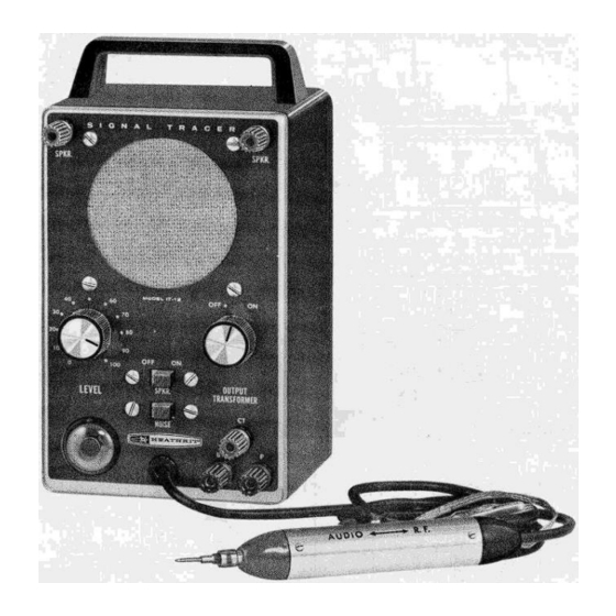
- Page 3 Page 1 ASSEMBLY AND OPERATION OF THE HEATHKIT VISUAL-AURAL SIGNAL TRACER MODEL IT-12 SPECIFICATIONS Power Supply………………………………………… Transformer operated Power Requirements 117 volts AC, 50-60 cps, 25 watts. Tube Complement VI - 12AX7 high gain dual triode, input cascade amplifier. V2 - 12CA5 beam power output tube.
- Page 4 Page 2...
- Page 5 Output level indicator. CIRCUIT DESCRIPTION The Heathkit Signal Tracer is a transformer operated, quality instrument, consisting primarily of a high-gain audio amplifier. A built-in 3-1/2" speaker is provided for sound and an electron ray tube permits visual observation of the output level.
- Page 6 Limits of +100 and -20 are common for electrolytic condensers. The parts furnished with your Heathkit have been specified so as to not adversely affect the operation of the finished instrument. The Signal Tracer is not difficult to construct but it is extremely important that particular emphasis be placed on the desirability of following parts placement and wiring dress as shown in the manual.
- Page 7 TYPE SOLDER. PROPER SOLDERING PROCEDURE Only a small percentage of Heathkit purchasers find it necessary to return an instrument for factory service. Of these, by far the largest proportion function improperly due to poor or-improper soldering. Correct soldering technique is extremely important. Good solder joints are essential if the performance engineered into the kit is to be fully realized.
- Page 8 Page 6 To make a good solder joint, the clean tip of the soldering iron should be placed against the joint to be soldered so that the terminal is heated sufficiently to melt solder. The solder is then placed against both the terminal and the tip of the iron and will immediately flow out over the joint.
- Page 9 Page 7 HOW TO MAKE PROPER SOLDER CONNECTION Take these precautions and use reasonable care during assembly of the kit. This will insure the wonderful satisfaction of having the instrument operate perfectly the first time it is turned on. In the step-by-step procedure the abbreviation "NS" indicates that the connection should not be soldered as yet, for other wires will be added.
- Page 10 Page 8 PANEL ASSEMBLY ( ) Locate the short 6/32 screw and set aside to be used later. ( ) Locate the front panel and position it as shown in Pictorial 1. ( ) Mount binding post A using a 6-32 nut. Position solder lug as shown in Pictorial 1. ( ) In like manner, mount binding post F, G and H.
- Page 11 Page 9 ( ) Mount the output transformer on the speaker so the two black wires are next to the voice coil terminals. Use 6-32 hardware. ( ) Mount the speaker and the speaker grill to the panel. Place a spacer washer between speaker and grill. At the same time mount ground lug B.
- Page 12 Page 10 CHASSIS ASSEMBLY NOTE: When mounting wafer tube sockets, be sure to mount each socket from the top of the chassis. If by mistake the sockets are mounted so the lugs pass through the chassis, they will short to the chassis where they pass through the mounting hole.
- Page 13 Page 11 ( ) Slip the two speed nuts J and K over the corners of the rear apron of the chassis. Make sure that the flat side of the clip is towards the back and the holes in the clips are centered over the holes in the chassis. ( ) Temporarily, mount the 1 meg level control Rl using a control solder lug.
- Page 14 Page 12 ( ) Connect one end of a 2" length of bare wire to pin 3 (Sl) of VI tube socket. Feed the other end through the center ground lug (S2), through pin 9 (S2) and connect to lug 2(NS) of terminal strip X. ( ) Cut two 6"...
- Page 15 Page 13 ( ) Connect one lead of a 68 K ohm resistor (blue-grey-orange) to pin 6 (NS) of VI. ( ) Connect the other lead to lug 2 of C7 (S4). Use sleeving on both leads. Connect one lead of a .005 mfd ceramic disc condenser to pin 2 (S2) of VI.
- Page 16 Page 14 ( ) Install the line cord strain relief in hole M. See Detail 5A. PREPARING THE EYE TUBE ASSEMBLY ( ) Start the two #6 sheet metal screws in the eye tube mounting bracket. ( ) Clip off the prongs of the spring tube holder as indicated in Figure 2.
- Page 17 Page 15 ( ) Cut 2" off the red wire and strip both ends of all the wires. ( ) Connect the blue wire to pin 2 (Sl) of the eye tube. ( ) Connect the red wire to pin 4 (S2). ( )Connect the green wire to pin 5 (Sl).
- Page 18 Page 16 ( ) Slip the length of flat braid through the probe end and bend over as shown. Wrap a short length of bare wire around the flat braid and the cable shield and solder. Cut off excess cable shield. Do not cut off braid. ( ) Solder an alligator clip to the other end of the braid.
- Page 19 Page 17 ( ) Connect the blue transformer wire to terminal G (S3). ( ) Feed the probe cable through grommet I and connect the inner conductor to lug 1 (S3) of terminal strip X. Connect the cable shield to lug 2 (S4) ( ) Twist the green and brown leads from the eye tube socket and connect the green lead to lug 3 (S3) of terminal strip Q.
- Page 20 USING THE SIGNAL TRACER The IT-12 Signal Tracer is one of the simplest, yet most effective instruments the service tech-nician can use for rapid, accurate trouble-shooting in radio and TV circuits. The tracer is of the untuned type to simplify operation thus holding control manipulation to an absolute minimum.
- Page 21 Page 19 gain setting of the tracer. These combined conditions result in the hearing of a high hum level in the tracer when the probe is connected to the plate. On some receivers the hum over-rides the signal making it necessary to move the probe to the secondary of the input IF transformer, (pin 1 of tube B) in order to check the gain of the first stage.
- Page 22 Page 20 Noise Locator A rather unique and definitely useful application of the Signal Tracer is its ability to locate noisy and intermittent components in various circuits. Basically the noise locatmg feature of the signal tracer permits the application of a DC test voltage to any component in the receiver circuit, and the action of the DC voltage in the component is picked up and amplified in the signal tracer itself.
- Page 23 Page 21 There is practically no limit to the variety of useful applications afforded by this feature of the signal tracer. It is suggested that the service technician further investigate other test procedures where application of a DC voltage to a component in conjunction with a high gain amplifier will permit observation of voltage action.
- Page 24 The Heathkit Signal Tracer will prove itself an extremely useful and versatile addition to any service shop. It is earnestly suggested that the user thoroughly familiarize himself with all phases of its operations, so that he may obtain maximum benefit from his investment in this instrument.
- Page 25 Page 23...
- Page 26 Page 24...
- Page 27 Page 25...
- Page 28 Page 26...
- Page 29 Please do not return parts to the factory unless they are requested. If it is convenient, personally deliver your kit to a Heathkit Parts that are damaged through carelessness or misuse by the kit Electronic Center.
Need help?
Do you have a question about the IT-12 and is the answer not in the manual?
Questions and answers