Nordyne M1B Series Owner's Manual & Installation Instructions
Downflow, direct vent (sealed combustion) forced air gas and oil furnaces
Hide thumbs
Also See for M1B Series:
- Owner's manual and installation instructions (40 pages) ,
- Installation instructions manual (40 pages) ,
- Installation instructions manual (40 pages)
Table of Contents
Advertisement
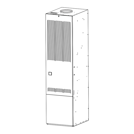
Downfl ow, Direct Vent (Sealed Combustion)
Forced Air Gas and Oil Furnaces
Owners Manual/Installation Instructions
Series M1B, M1G, M1M and M1S
For installation in:
1. Manufactured Homes
2. Recreational Vehicles, Park Models,
Manufactured Buildings
3. Modular Homes/Buildings
WARNING:
If the information in this manual is not
followed exactly, a fi re or explosion
may result causing property damage,
personal injury or loss of life.
– Do not store or use gasoline or
other fl ammable vapors and liquids
in the vicinity of this or any other
appliance.
– WHAT TO DO IF YOU SMELL GAS
• Do not try to light any appliance.
• Do not touch any electrical switch;
do not use any phone in your build-
ing.
• Immediately call your gas supplier
from a neighbor's phone. Follow the
gas supplier's instructions.
• If you cannot reach your gas sup-
plier, call the fi re department.
– Installation and service must be
performed by a qualifi ed installer,
service agency or the gas sup-
plier.
WARNING:
Should overheating occur, or the gas
supply fail to shut off, shut off the man-
ual gas valve to the appliance before
shutting off the electrical supply.
LEAVE THESE INSTRUCTIONS WITH THE HOMEOWNER.
WARNING:
Improper installation, adjustment,
alteration, service or maintenance
can cause injury or property damage.
Refer to this manual. For assistance
or additional information consult a
qualifi ed installer, service agency or
the gas supplier.
Advertisement
Table of Contents

Related Manuals for Nordyne M1B Series


Summary of Contents for Nordyne M1B Series
- Page 1 Downfl ow, Direct Vent (Sealed Combustion) Forced Air Gas and Oil Furnaces Owners Manual/Installation Instructions Series M1B, M1G, M1M and M1S For installation in: 1. Manufactured Homes 2. Recreational Vehicles, Park Models, Manufactured Buildings 3. Modular Homes/Buildings WARNING: If the information in this manual is not followed exactly, a fi...
-
Page 2: Table Of Contents
TABLE OF CONTENTS 1. SPECIFICATIONS ..................3 2. OWNERS INFORMATION ................3 3. MANUFACTURER WARRANTY, OWNER RESPONSIBILITY ....3 4. INSTALLATION STANDARDS ..............5 5. UNIT LOCATION ..................6 6. MINIMUM CLEARANCES ................6 7. RETURN AIR PROVISIONS ..............6 8. AIR DISTRIBUTION SYSTEMS ...............8 9. ROOF JACK SELECTION ................8 10. -
Page 3: Specifications
(PO Box 46911, St. Louis, MO 63146) if to the M1 series of furnaces. you are not able to locate a source for NORDYNE manufactured housing products in your area. Multi-speed blower assemblies as shown in Table 3 have been certifi... - Page 4 Some specifi c examples of service calls which 7. Furnace problems caused by installation of cannot be included in warranty payments are: an air conditioner, heat pump or other air comfort devices. 1. Converting the furnace to use another type 8.
-
Page 5: Installation Standards
Blower / Motor Assembly A/C Capacity Part No. Blower Wheel Motor-Hp 903773 10 x 8 2, 2½ & 3 903413 11 x 8 2, 2½, 3 & 4 903414 11 x 8 2, 2½, 3, 4 & 5 Table 3. Field Installation Blower Assemblies CAUTION: 6"... -
Page 6: Unit Location
CAUTION: void all warranties. HAZARD OF ASPHYXIATION: Nega- Furnace may be installed on combustible fl oor- ing when using NORDYNE Duct Connectors tive pressure inside the closet, with (see Section 10). closet door closed and the furnace blower operating on high speed, shall When installed in a residential garage, the fur- be no more negative than minus 0.05... - Page 7 f. Noncombustible pans having 1” upturned a. Regardless of the location, the return air fl anges are located beneath openings in a opening into the closet shall not be less than fl oor duct system. specifi ed in the appliance’s listing. g.
-
Page 8: Air Distribution Systems
120”). An internal duct register and open louver area to ob- roof jack extension (p/n 901935 - 10”, p/n tain necessary airfl ow. Use NORDYNE’s 903107 - 18”) can be used to increase roof certiduct program to determine proper duct jack height. -
Page 9: Installation
b. Select appropriate model from Table 7 13). Installation procedures are suggested for which matches X-dimension of the fl oor typical furnace installations and need not be cavity. To maximize air delivery, remove followed in the exact listed sequence. reducer “C” (see Figure 11) to obtain the largest open area that will fi... - Page 10 CEILING AND ROOF OPENINGS 13-1/2" ALT. FUEL LINE HOLES 10" FLOOR OPENING 23 -1/4" FUEL LINE HOLE Figure 12. Closet or Alcove 20" 14-1/2" 2-3/4" REAR WALL OF CLOSET OR ALCOVE FLOOR CUT-OUT FOR DUCT CONN. FLOOR CUT-OUT FUEL-LINE FOR OPTIONAL COOLING COIL 3/4"...
- Page 11 along the center line of furnace and fl oor c. Locate center of fuel line hole, measured 23- opening. (See Figure 13) 1/4” from the rear wall and 6-5/8” to the left b. Cut ceiling and roof holes as follows: of center of the fl...
- Page 12 d. Cut out duct opening 1/4” larger than area ALTERNATE ATTACHMENT METHODS marked. This procedure may also be used to install a INSTALL FURNACE MOUNTING PLATE furnace duct connector to narrow metal ductwork a. Place mounting plate (supplied within duct where insuffi...
-
Page 13: Installation Of Transit-Mode Venting System
INSTALL FURNACE vent collar and restrict the fl ow of furnace a. Remove furnace outer door(s) and bottom fl ue products. fuel line knockout. b. Place furnace onto duct connector and center Attach Roof Flashing: If necessary, shift roof with fl oor opening. fl... -
Page 14: Electrical Wiring
• To furnace fl ame observation door (Gas or Oil) • To furnace wall thermostat SLIDE FURNACE MTG. PLATE TABS ALL THE WAY BACK ONTO MTG. PLATE MANUFACTURED HOME SITE SECURE FURNACE a. Transit-mode weather cap to be removed and WITH 2 FASTENERS AT FRONT CORNER HOLES upper Roof Jack crown installed (See Figure... - Page 15 Power supply circuit to the furnace must be CAUTION: installed and grounded in accordance with the National Electrical code (ANSI-C1/NFPA-70), or Label all wires prior to disconnection Canadian Electric Code Part 1 (CSA 22-1) and all local codes having jurisdiction. when servicing controls.
-
Page 16: Fuel Piping
Five-conductor thermostat wire is recommended 14. FUEL PIPING for 24 volt low-voltage circuit (2-wire is required Sizing and installation of fuel lines must be in ac- for furnace only; 5-wire for heating and optional cordance with federal, state and local regulations. cooling systems). - Page 17 to 3-1/2” W.C. by the pressure regulator in the T’STAT Recommended T’STAT Wire gas valve. The maximum inlet pressure for the Wire Gauge Length (Unit to T’STAT valve is 13” W.C. 2-Wire 5-Wire (Heating) (Heating/Cooling) For L.P. gas, pressure to the gas valve must be more than 11”...
- Page 19 Fuel Line Hook-Up: One Line System How to Eliminate Air Leaks The one line system is highly recommended To eliminate problems caused by air in the oil line, where vertical lift, from bottom of tank to pump, all connections in the oil supply line and all plugs, is not more than eight feet.
-
Page 20: Flue Gas Sampling
DO NOT USE GASOLINE, CRANKCASE OIL, SAFETY INFORMATION OR ANY OIL CONTAINING GASOLINE. FOR YOUR SAFETY READ BEFORE LIGHT- ING. WARNING: a. The fi rst lighting of the furnace after any Failure to keep supply of oil clean home setup must be performed by a quali- by various procedures described fi... - Page 21 In the event of any fl ashback or explosion, steps “d” through “h” above. If the lever does immediately shut off the furnace and call your not spring back when released, stop and im- service technician. mediately call your service technician or gas supplier.
- Page 22 SEQUENCE OF OPERATION FOR STAND- ING PILOT W/INDUCED DRAFT BLOWERS a. STOP! Read the SAFETY INFORMATION. MODELS b. Set the thermostat to the lowest setting. a. On a call for heat, the thermostat contacts c. Turn off all electric power to the appliance. close, supplying 24 VAC to the relay.
- Page 23 close, supplying 24 VAC between terminals AVERTISSEMENT: “C” and “W” of the control module, which starts combustion motor. b. When the inducer starts, the air pressure En case de température excessive, switch closes at -0.20”WC differential pressure ou sail est impossible de cooper and energizes the control.
- Page 24 8. Honeywell - turn knob on gas control counter 5. The circulating air blower will energize after clockwise to “ON.” Robertshaw - push the the temperature fan switch closes. gas control lever to “ON.” 6. The furnace runs until the call for heat is 9.
-
Page 25: Service Guide
c. Set the On-Off Switch to “OFF.” of the safety ignition timing period, the control d. Honeywell - turn gas control knob clockwise shuts the burner off and enters “lock-out.” to “OFF” Robertshaw - Push the gas control lever to “OFF.” 6. - Page 26 COMBUSTION AIR Electrode Setting (Oil Gun Only) In order for the fl ame to burn effi ciently, it must Poor ignition of the oil spray may result if the receive adequate combustion air. The amount electrodes are not adjusted as shown in Figure of combustion air required will vary depending 32.
- Page 27 top of the gas valve. Invert the converter. (For Robertshaw “LP” the red ring will be located at the bottom Valve and the “LP” stamping on the converter will appear right side up.) Then screw converter back into the regulator, hand tight plus 1/8 turn, and replace the black cover onto the converter top to protect the threads.
- Page 28 Control Module Status Indicators - M1M Series Control Status The Red LED labeled “STATUS” is provided to indicate system faults. Steady ON: Control OK Steady OFF: No power Rapid fl ash: False fl ame or internal control fault One fl ash: Limit switch is open Two fl...
- Page 29 e. Check for gas supply - gas line valve on, Main Flame Is Not Burning Properly control lever on. a. Check the manifold gas pressure. b. Check for the correct main burner orifi ce. Control Module Is Powered— - See the nameplate SPECIFICATION. Ignitor Does Not Heat Up c.
- Page 30 it will be affected by another heat source. LED Flashes Cad Cell b. Check for clean fi lter and proper air fl ow. Ohms Resistance c. Check burner for proper gas fi ring rate. 0-400 d. Be sure unit is not undersized for its thermal load.
-
Page 31: Maintenance
Do not obstruct any return air open- installations illegal. Listed NORDYNE ings, including the grille on the fur- air conditioning components are nace. To do so may cause the furnace specifi... - Page 32 Figure 37. Coil Cavity Damper (Non-Platinum Series Only) Figure 38. Damper without Coil Cavity (Non-Platinum Series Only) M1* A/C Ready M1* A/C Ready Thermostat Thermostat Furnace Furnace White White White White Green Green Green Green Yellow Grey Yellow Grey Route Thermostat wire to intended Platinum Series AC/HP location.
-
Page 33: Optional Accessories
Clean or replace the oil filter element at the oil tank. NORDYNE unit is available that has been de- f. Adjust the burner for top effi ciency and check signed specifi cally for manufactured housing to make sure all fi... -
Page 40: Equivalent Orifice Sizes At High Altitudes
21. EQUIVALENT ORIFICE SIZES AT HIGH ALTITUDES (Includes 4% Input Reduction for Each 1,000 Feet) FURNACE ORIFICE SIZE AND ALTITUDE - FEET MODEL OUTPUT CAPACITY SEA LEVEL 2000 3000 4000 5000 6000 7000 8000 9000 10000 ORIFICE SIZE - NAT. GAS M1M/G 056 ORIFICE SIZE - LP OUTPUT- MBTUH 45.4...
Need help?
Do you have a question about the M1B Series and is the answer not in the manual?
Questions and answers