Table of Contents
Advertisement
Quick Links
Advertisement
Table of Contents

Subscribe to Our Youtube Channel
Summary of Contents for FlyTech POS 360 Series
- Page 1 User Manual Revision v1.3 July 2009 Point-of- Sale Hardware System...
- Page 2 Copyright 2009 July All Rights Reserved Manual Version 1.3 P/N: 3LMPP3600313 The information contained in this document is subject to change without notice. We make no warranty of any kind with regard to this material, including, but not limited to, the implied warranties of merchantability and fitness for a particular purpose.
- Page 3 Safety IMPORTANT SAFETY INSTRUCTIONS 1. To disconnect the machine from the electrial power supply, turn off the power switch and remove the power cord plug from the wall socket. The wall socket must be easily accessible and in close proximity to the machine. 2.
- Page 4 CAUTION ON LITHIUM BATTERIES There is a danger of explosion if the battery is replaced incorrectly. Replace only with the same or equivalent type recommended by the manufacturer. Discard used batteries according to the manufacturer’s instructions. LEGISLATION AND WEEE SYMBOL 2002/96/EC Waste Electrical and Electronic Equipment Directive on the treatment, collection, recycling and disposal of electric and electronic devices and their components.
- Page 5 Revision History Changes to the original user manual are listed below: Version Date Description • 2007 March Initial release • 2007 May System Disassembly updated • 2007 Cover page updated • September Connector Pin Definition updated • 2007 Cash Drawer Power Setting 1.2a September Correction...
-
Page 6: Table Of Contents
Table of Contents 1 Item Checklist ......1 1-1 Standard Items ............1 1-2 Optional Items ............2 2 System View......... 3 2-1 Front View ..............3 2-2 Side View..............4 2-3 Rear View ..............4 2-4 Bottom View ..............5 2-5 I/O View ..............5 3 Driver Installation ......6 3-1 Driver List ..............6 3-2 Chipset Driver Installation ..........7 3-3 USB 2.0 Driver Installation.........8... - Page 7 8 BIOS Settings......43 8-1 BIOS Setup Utility ............43 8-2 Starting the BIOS Setup...........43 8-3 When a Problem Occurs..........43 8-4 BIOS Main Menu .............43...
-
Page 8: Item Checklist
Item Checklist Take the system unit out of the carton. Remove the unit from the carton by holding it by the foam inserts. The following contents should be found in the carton: Standard Items a. Driver CD b. User Manual c. -
Page 9: Optional Items
Optional Items a. CF card holder b. MSR c. 2-in-1 MSR + Finger Print Module d. 2-in-1 MSR + iButton Module e. 10.4", 12.1" LCD Second Display f. VFD... -
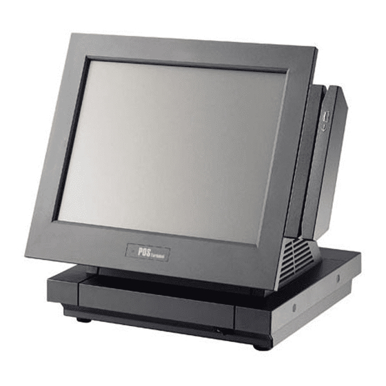
Page 10: System View
System View Front View Power LED Power Switch Button... -
Page 11: Side View
Side View Tilt Angle 65° ~ -25° Pole type VFD Small Footprint Rear View Speaker Holes Rear I/O... -
Page 12: Bottom View
Bottom View Rubber Foot VESA mounting holes I/O View MIC in Line out USB (4) COM (4) DC Jack Cash Parallel Drawer Note: The maximum current that can be drawn from each COM port is 500 mA. -
Page 13: Driver Installation
Driver Installation Driver List B78 V2.2 Driver List Folder/File File Description <CD>:\ POS360_B78.htm Driver List <CD>:\COMMON\INTEL\Chipset\i8xx Chipset Driver <CD>:\COMMON\INTEL\USB20 USB 2.0 Driver <CD>:\COMMON\INTEL\VGA\i85x VGA Driver <CD>:\COMMON\Ac97_codec\Realtek\ALC202A Audio Driver <CD>:\COMMON\ POS_Touch POSTouch Driver <CD>:\COMMON\ELO_Touch ELO Touch Driver <CD>:\COMMON\Lan_driver\Realtek_PCI 10/100/1000Mb LAN Driver -The following procedures are for Windows 2000/XP, other platforms are similar. -
Page 14: Chipset Driver Installation
Chipset Driver Installation a. Click “Chipset” in the Driver List b. Double-click menu of POS360 B78. “infinst_enu_6.0.1.1002.exe” on the My computer window. c. Click the “Next” button on the d. Click the “Yes” button on the License Welcome window. Agreement window. e. -
Page 15: Usb 2.0 Driver Installation
USB 2.0 Driver Installation OS Requirements USB 2.0 requirements USB 2.0 drivers are provided in Service Pack 1 (SP1) Windows XP for Windows XP, which is available through Windows Update. USB 2.0 drivers are available through Windows Update Windows 2000 or Service Pack 4. - Page 16 a. Right click My Computer on the b. Select “Hardware” ”Device desktop and select “properties” Manager” on system properties c. Select ”Other Devices” “Universal Serial Bus (USB) Controller” ”Properties” on Device Manager d. Select “Device” “Update Driver e. Click the ”Next” button on the welcome window.
- Page 17 f. Select “Search for a suitable…”and g. Select “Specify a location” and click click the “Next” button on the Install the “Next” button on the Locate Hardware Device Drivers window Driver Files window. h. Press “Browse” to select the driver i.
-
Page 18: Vga Driver Installation
VGA Driver Installation a. Click “Win2K_XP” of “VGA” section b. Click “Run” when the “File in the Driver List menu. Download – Security Warning” dialog pops up. c. Click the “Next” button on the d. Click the “Next” button on the Intel(R) Chipset Graphics Driver Intel(R) Graphics Media Accelerator Software- Install Shield(R) Wizard... -
Page 19: Audio Driver Installation
Audio Driver Installation a. Click “Win9X,ME,2K_XP” of the b. Double-click “A3.71” on the My “Audio” section in the Driver List Computer window. menu. c. Double-click “wdm_a371.exe” on the d. Click “Next” button on the Realtek My Computer window. AC’97 Audio Setup window. e. -
Page 20: 10/100/1000Mb Lan Driver Installation
10/100/1000MB LAN Driver Installation a. In the “Realtek RTL8110” section, b. Double-click “v709” click on Win9X, ME, 2K, XP c. Double-click Setup.exe d. Click the Finish button on the Maintenance Complete window. e. Click the OK button and restart your system. -
Page 21: Elo Touch Driver Installation
ELO Touch Driver Installation a. In the “ELO” section, click on b. Click “Install Touch Driver” on “FT “Windows”. Touch Auto Install V1.0.2.0” window to detect the touch type in your system. d. A “WinZip Self-Extractor” dialog will c. Click “Install Touch Driver”. pop up. - Page 22 g. Click “Next”. h. Check the “Install Serial Touchscreen” Drivers” check box and click “Next”. i. Click “Yes” to accept the “End User j. Examining serial ports on the License Agreement”. computer k. Check the box “Auto-detect Elo l. The computer is searching for a devices”...
- Page 23 m. Touchscreen found on “COM5”. n. Click “Next” to complete the driver Click “Next”. installation o. Driver is installing p. The driver installation and setup are now complete. Click “Finish” to start the touchscreen calibration. q. Follow the instructions on the screen r.
-
Page 24: Postouch Driver Installation
POSTouch Driver Installation a. In the “Touch Screen auto…” section, b. Click “Install Touch Driver” on “FT click “Windows”. Touch Auto Install V1.0.2.0” window to detect the touch type in your system. c. “FT Touch Auto Install” program will d. Click ”Next”. detect what touch type and interface being installed on the system. - Page 25 g. Select the shortcut folder for the touch h. Click ”Next”. utility driver and click ”Next”. i. Click ”Next”. j. The computer is installing the touch driver k. Click ”Continue Anyway” button. l. The serial ports are scanned for a touch device.
- Page 26 m. Click ”Finish”. n. Click ”OK” to restart the computer and finish the touch utility installation. o. The computer has restarted. Click on p. Select the Device tab. the ”Start” button, select “Programs”, then select ”Touchutility”. q. Click on the 3 points or the 9 points r.
- Page 27 s. Touch anywhere on the screen to save the calibration.
-
Page 28: Peripherals Installation
Peripherals Installation MSR Module Installation The MSR (Magnetic Card Reader) unit is tested and can be supplied at your request. This MSR is removed during transportation and can be connected by the user. There are two types of MSR Module: RS232 type and keyboard type. a. - Page 29 b. Secure the grounding cable (1) with the screw (1) and connect the MSR cable to the respective connector on the System. c. Place the MSR into the right position of the System and fasten the screws (2) to fix the MSR module.
-
Page 30: 2-In-1 Msr + Finger Print Module Installation
2-in-1 MSR + Finger Print Module Installation a. Open the MSR Cover first (See Chapter 4.1 (a)) b. Connect the Finger Print Cable (1) to the connector on the System. c. Fasten the screw (2) and place the Module into the right position of the System. -
Page 31: Second Display Installation
Second Display Installation VFD Hole VFD Cover a. Connect the VGA Cable to the Second Display. b. Open the VFD cover on the System. c. Thread the VGA cable through the VFD hole. d. Connect the VGA cable to the System. e. -
Page 32: Vfd Installation
VFD Installation VFD Cable (RJ45) Screws x 2 VFD Pole Wheel Shaft Assembly Accessories of VFD Kit a. Thread the VFD Cable (RJ45) through the VFD Pole. b. Connect the VFD cable to the connector on the I/O Panel of the System. - Page 33 c. Turn the VFD bottom up and connect the other side of the VFD cable to the connector (RJ45) on the VFD. d. To align and attach the VFD onto the right position of the VFD Pole head. e. Detach one plastic wheel from the Wheel Shaft Assembly. f.
-
Page 34: Cash Drawer Installation
Cash Drawer Installation You can install a cash drawer through the cash drawer port. Please verify the pin assignment before installation. 4-6-1 Cash Drawer Pin Assignment Signal DOUT bit0 DIN bit0 12V / 19V DOUT bit1 4-6-2 Cash Drawer Controller Register The Cash Drawer Controller use one I/O addresses to control the Cash Drawer. - Page 35 Bit 3: Reserved. Bit 2: Cash Drawer “DOUT bit0” pin output control. = 1: Opening the Cash Drawer = 0: Allow closing the Cash Drawer Bit 1: Cash Drawer “DOUT bit1” pin output control. = 1: Opening the Cash Drawer = 0: Allow closing the Cash Drawer Bit 0: Reserved Note: Please follow the Cash Drawer control signal design to control the Cash...
-
Page 36: System Disassembly
System Disassembly Replacing SATA HDD a. Loosen the thumb screws (2) to remove the Motherboard cover. b. Disconnect the SATA HDD Cable. c. Remove the screws (4) and detach the SATA HDD from the sheet metal chassis. d. Loosen the screws (4) on the both sides of the HDD metal bracket and replace the SATA HDD afterwards. -
Page 37: Replacing The Cf Card Holder (Optional)
Replacing the CF Card Holder (Optional) a. Loosen the thumb screws (2) to remove the Motherboard cover. b. Disconnect the IDE cable and remove the screws (2) to replace the CF card holder. -
Page 38: Replacing Motherboard & I/O Board
Replacing Motherboard & I/O Board a. Open the Motherboard Cover first (see Chapter 5.1(a)). b. Unlock the cable clips (2). c. Disconnect all the cables (8) - HDD, LVDS, Inverter, touch, VFD, MSR (if installed), LED light and LCD cables from the connectors on the Motherboard. - Page 39 f. Remove the screws (6) on each side to separate the metal chassis from the stand Base. g. Disconnect the power button cable. h. Remove the screws (4) and slide the Motherboard with I/O panel outward as the direction of the arrow shows.
-
Page 40: Replacing Inverter Board & Touch Screen Board
Replacing Inverter Board & Touch Screen Board a. Open the Motherboard cover and disconnect all the cables connected to the Motherboard first (See Chapter 5.3 (a) (b) (c)). b. Press and pull as the direction of arrows show to remove the hinge cover. c. - Page 41 f. Remove the screws (2) and disconnect the Cables (2) to take out the Touch Board.
-
Page 42: Specification
Specification Motherboard B78 v2.2 CPU Support Intel Celeron M ULV 600MHz/ 1GHz Chipset Intel 852GM + ICH4 System Memory 256MB DDR RAM, up to 2GB Graphic Memory Shared system memory up to 64MB LCD Panel LCD Size 12.1"TFT 15" TFT Brightness up to 400 cd / m²... - Page 43 Peripherals Customer Display Pole mounted type (VFD/ LCD type) Magnetic Card Reader 3 Tracks ( RS-232 (COM6) / PS2 interface ) Second Display 10.4" or 12.1" LCD Second Display Environment Operating Temperature 5°C ~ 35°C ( 41°F ~ 95°F ) Storage Temperature -20°C ~ 55°C (-4°F ~ 140°F) Operating Humidity...
-
Page 44: Jumper Settings
Jumper Settings B78 v2.2 Motherboard JP13 JP10 JP14... -
Page 45: B78 V2.2 Jumper Settings
B78 v2.2 Jumper Settings The diagram below illustrates the default jumper settings for the Main Board. An asterisk (*) indicates the default setting. 7-1-1 Connectors & Function Connector Function BAT1 CMOS Battery Base ( Use CR2023) Audio Line Out Audio MIC In Internal Power Switch Speaker &... - Page 46 COM2 RS232/485/422 Setting JP10 Function (1-2) (3-4) (5-6) (7-8) (9-10) (11-12) (1-2) (3-4) (4-6) (5-7) (7-8) (9-10) 2 4 6 8 10 1 3 5 7 9 ◎RS232 2 4 6 8 10 1 3 5 7 9 11 1 3 5 7 9 RS485 2 4 6 8 10 12 1 3 5 7 9 11...
- Page 47 COM3 & COM4 Power Setting Function (1-2) (3-4) (5-6) (7-8) (9-10) (11-12) 1 3 5 7 9 11 ◎RI 2 4 6 8 10 12 1 3 5 7 9 11 COM3 Pin10 2 4 6 8 10 12 1 3 5 7 9 11 +12V 2 4 6 8 10 12 1 3 5 7 9 11...
- Page 48 LCD ID Setting LVDS Panel # Resolution (1-2) (3-4) (5-6) (7-8) Bits Channel 1 3 5 7 1024 Single 2 4 6 8 1 3 5 7 1024 Single 2 4 6 8 1 3 5 7 Note: Panel 1 Jumper Setting is for SVA-NEC panel Panel 2 Jumper Setting is for other LCD Panel.
- Page 49 System Indicator Function (do not change) JP13 Function (1-2) (3-4) (5-6) (7-8) 1 3 5 7 ◎Disable 2 4 6 8 1 3 5 7 Enable 2 4 6 8 ◎ = Default Note: OPEN SHORT...
- Page 50 BIOS Settings BIOS Setup Utility The BIOS setup defines how the system is configured. You need to run this program the first time you configure this product. You may need to run it again if you change the configuration. You need to connect a PC keyboard to the keyboard connector to run the BIOS setup utility.
- Page 51 Standard CMOS Features Use this menu for basic system configuration. Advanced BIOS Features Use this menu to set the Advanced Features available on the system. Advanced Chipset Features Use this menu to change the values in the chipset registers and optimize the system’s performance.
- Page 52 Save & exit setup Save CMOS value changes to CMOS and exits setup. Exit without saving Ignores all CMOS value changes and exits setup.
Need help?
Do you have a question about the POS 360 Series and is the answer not in the manual?
Questions and answers