
Summary of Contents for ACT ACTpro MIFARE Series
- Page 1 ACTpro MIFARE Readers ACTpro MF 1030e - Slimline Proximity Reader ACTpro MF 1040e - Proximity Reader ACTpro MF 1050e - PIN & Proximity Reader ACTpro MF 1030PM - Reader Panel Mount Proximity Installation Manual...
-
Page 2: Table Of Contents
ACTpro MIFARE Readers Installation Manual Contents Page No. Specifications Table ................3 Product Description ................4 Reader Connections 1040e/1050e ............4 Reader Connections 1030e ..............5 CAT 5/6 Colour Code ................5 Clock & Data Entry and Exit Reader Wiring Diagrams ......6 Wiegand Entry and Exit Reader Wiring Diagrams ........ -
Page 3: Specifications Table
ACTpro MIFARE Readers Installation Manual Specifications Table MIFARE 1030e MIFARE 1030PM MIFARE 1040e MIFARE 1050e Connections Pigtail Terminal Block Terminal Block Terminal Block Dimensions 37 x 120 x 15mm 63 x 58 x 23mm 95 x 128 x 19mm 95 x 128 x 21mm W x H x D Mounting Mullion... -
Page 4: Product Description
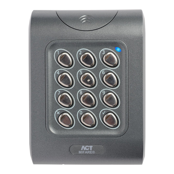
ACTpro MIFARE Readers Installation Manual Product Description ACT MIFARE classic readers support all ACT MIFARE cards and fobs. They can be confi gured to read serial, reverse serial or sector data from any third party MIFARE Classic card. • Compatible with ACT MIFARE cards and fobs •... -
Page 5: Cat 5/6 Colour Code
ACTpro MIFARE Readers Installation Manual Reader Connections - ACTpro MIFARE 1030e ACTpro MIFARE 1030e is supplied with 3m pigtail cable. SENSE (White) CLOCK/D1 (Green) DATA/D0 (Blue) +12V (Red) 0V/GND (Black) RED LED (Brown) GREEN LED (Yellow) (Orange) Programming Sector/Serial (Purple) ISP (Grey) - Unused CAT 5/6 Colour Code The following is suggested colour coding if using CAT5 or CAT6 cabling. - Page 6 ACTpro MIFARE Readers Installation Manual Clock & Data Entry Reader - Wiring SENSE (White) CLOCK / D1 (Green) DATA / D0 (Blue) +12V (Red) OV / GND (Black) BUZZER INPUT (Not available on 1030e) RED (Brown) GREEN (Yellow) Clock & Data Exit Reader - Wiring SENSE (White) CLOCK / D1 (Green) DO NOT CONNECT SENSE (White cable)
- Page 7 OV / GND (Black, White) BUZZER INPUT (Not available on 1030e) RED (Brown) GREEN (Yellow) IMPORTANT: To put ACT readers into wiegand mode connect the SENSE on the reader to 0V/GND. WIEGAND Exit Reader - Wiring SENSE (Blue) CLOCK / D1 (Green)
-
Page 8: Reader Configuration
Not Connected Sector Reader The default sector reader operation reads a numbers encoded into Sector 1 of the MIFARE cards and fobs. The ACT MIFARE readers can be programmed to read any specified sector data. See section on reader re-programming. -
Page 9: Reader Reprogramming
Reader Re-programming The ACTpro MIFARE readers will ship from the factory pre-configured to read ACT MIFARE cards and fobs. The ACT pro MIFARE reader can also be reconfigured for serial or reverse-serial by repositioning the jumpers. (See section on reader configuration) -
Page 10: Power On Beep Codes
Note: If the reader has been re-programmed (see next page), then a series of notes is played after the Second Beep Set, this indicates that the default programming to read ACT MIFARE cards has been changed. Copyright © 2016 Access Control Technology Ltd. Part No.18-00102 Issue 1... -
Page 11: 1030E Mounting Diagram
ACTpro MIFARE Readers Installation Manual ACTpro MIFARE 1030PM Mounting Diagram Mounting Instructions 1. Place the VR screen printed perspex over the four studs on the back of the audio entry panel. 2. Place the ACTpro MIFARE panel mount reader over the four studs. 3. - Page 12 ACTpro MIFARE Readers Installation Manual ACTpro 1030PM MIFARE Panel Mount reader connections to the ACTpro Door Controllers & Door Stations Jumper Pins 1 + 2: Sector operation Sector Mode Serial Mode Jumper Pins 2 + 3: Serial operation No Jumper: Byte reversed serial operation +12/24V DATA...
- Page 13 ACTpro MIFARE Readers Installation Manual ACTpro MIFARE 1040e/1050e Surface Mount Diagram Security screw supplied with the unit Place the cap onto the unit and push firmly in place The surface mount collar is mounted on the wall using the fixing kit supplied in the box. Place the reader / keypad onto the surface mount collar and clip down into place.
- Page 14 ACTpro MIFARE Readers Installation Manual ACTpro MIFARE 1040e/1050e Flush Mount Diagram Copyright © 2016 Access Control Technology Ltd. Part No.18-00102 Issue 1...
- Page 15 ACTpro MIFARE Readers Installation Manual ACTpro MIFARE 1040e/1050e Flush Mounting to UK Pattress Box Copyright © 2016 Access Control Technology Ltd. Part No.18-00102 Issue 1...
- Page 16 While every effort has been taken by ACT to ensure the accuracy of the information contained within this document, ACT assumes no responsibility for any errors or omissions.
Need help?
Do you have a question about the ACTpro MIFARE Series and is the answer not in the manual?
Questions and answers