Advertisement
E E n n d d u u r r a a n n c c e e
E E n n d d u u r r a a n n c c e e
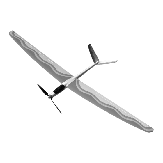
The E E n n d d u u r r a a n n c c e e 4 4 0 0 0 0 is a electric
powered glider that can perform like a true sail plane. With its
aileron controls and at "V" tail, this glider will satisfy any pilots
dream of flying.
A radio-controlled model is not a toy and is not intended for persons under 16 years old. Keep
this kit out of the reach of younger children, as it contains parts that could be dangerous. A radio-
controlled model is capable of causing serious bodily injury and property damage. It is the buyer's
responsibility to assemble this aircraft correctly and to properly install the motor, radio, and all other
equipment. Test and fly the finished model only in the presence and with the assistance of another
experienced R/C flyer. The model must always be operated and flown using great care and common
sense, as well as in accordance with the Safety Code of the Academy of Model Aeronautics (5151
Memorial Drive, Muncie, IN 47302, 1-800-435-9262). We suggest you join the AMA and become prop-
erly insured prior to flying this model. Also, consult with the AMA or your local hobby dealer to find an
experienced instructor in your area. Per the Federal Communications Commission, you are required
to use only those radio frequencies specified "for Model Aircraft."
Carl Goldberg Products, Ltd. has inspected and certified the components of this aircraft. The company urges the buyer to per-
form his own inspection, prior to assembly, and to immediately request a replacement of any parts he believes to be defective for
their intended use. The company warrants replacement of any such components, provided the buyer requests such replacement
within a period of 90 days from the date of purchase and provided the defective part is returned, if so requested by the company.
No other warranty, expressed or implied, is made by the company with respect to this kit. The buyer acknowledges and under-
stands that it is his responsibility to carefully assemble the finished flying model airplane and to fly it safely. The buyer hereby
assumes full responsibility for the risk and all liability for personal or property damage or injury arising out of the buyer's use of the
components of this kit.
CARL GOLDBERG PRODUCTS, LTD.
P.O. Box 818 Oakwood GA 30566 Phone #678-450-0085 Fax # 770-532-2163 www.carlgoldbergproducts.com
©copyright 2004
WARNING
LIMITED WARRANTY
1
4 4 0 0 0 0
4 4 0 0 0 0
Advertisement
Table of Contents

Related Manuals for Carl Goldberg Products Endurance 400

Summary of Contents for Carl Goldberg Products Endurance 400
- Page 1 LIMITED WARRANTY Carl Goldberg Products, Ltd. has inspected and certified the components of this aircraft. The company urges the buyer to per- form his own inspection, prior to assembly, and to immediately request a replacement of any parts he believes to be defective for their intended use.
-
Page 2: Preparing For Assembly
USING THIS INSTRUCTION MANUAL COVERING Before you begin assembling your E E n n d d u u r r a a n n c c e e 4 4 0 0 0 0 ARF, The E E n n d d u u r r a a n n c c e e 4 4 0 0 0 0 ARF is covered in a premium polyester take some time to read through this entire instruction book. - Page 3 Caution: Before starting, carefully go over all high stress areas with an epoxy or wood glue to confirm all areas are well glued. Warnings about Lithium Polymer batteries NEVER charge Lithium Polymer batteries with a charger designed for NiCd, NiMH, or any other type of battery chemistry. Use ONLY the chargers listed under REQUIRES or equivalent substitutes.
- Page 4 Wing Installing Ailerons Insert the CA hinges half way into the wing and the ailerons. (Use a pin inserted into the middle of the hinge to help keep the hinge in Collect the following parts: the middle.) (2) Wing ( Left & Right) Make sure that the aileron is against the wing (2) Ailerons ( Left &...
- Page 5 Tape the hex nut to the bottom of the wing. Insert the servo wire plug into the hole in the rib in the aileron servo hole. Slowly pull the servo extension through the wing till it exits the center wing rib hole. HINT: Look through the hole in the wing and pull back and forth on the string and the extension wire, too feed it through the wing.
- Page 6 Using rubbing alcohol, clean the bottom of the servo where the double sided tape will be Thread the nylon clevis onto the threaded applied. rod.. Making sure that the both the wing and the Attach the clevis to the wooden control horn. servo are dust free, apply a piece of double sided tape to the servo.
-
Page 7: Elevator & Pushrod
Repeat this process with the other elevator. Align the two control horns so they are even with each other. (See Photo) Carefully pull the elevators back out of the “V” tail and glue the control horns in place. Re-insert the hinges into the elevators and placet them back onto the “V”... -
Page 8: Speed Control
Battery & Receiver Location Lay the pushrod on the table top just like it sits inside the fuselage. Bend the pushrod 90 degrees at the mark you just made. Bend the wire so that you insert the pushrod thru the servo arm. (See Photo Slide the battery behind the elevator above) servo. -
Page 9: Control Throws
CG Location and Control Throws The E E n n d d u u r r a a n n c c e e 4 4 0 0 0 0 balance point is 2-1/4 to 2-1/2” back from the leading edge of the wing next to the fuselage. It is always better to fly slightly nose heavy, then slowly move the balance point back till the plane flies the way you like it. - Page 10 Finally, make sure that everything on your aircraft is The Endurance 400 was designed for long, slow, relaxed neatly and firmly in place-motor fastened down, servos flying - not loops or similar aerobatic maneuvers. Save...
Need help?
Do you have a question about the Endurance 400 and is the answer not in the manual?
Questions and answers