
Summary of Contents for BILOXXI RHP25
- Page 1 Instruction manual Hand pallet truck RHP25 Original instructions (IM)237‐000413_RHP25_GB-IM_V4_150626.indd 1 7/3/15 17:09...
- Page 2 Dear Customer, Congratulations on your purchase of this BILOXXI product. Please take a few minutes before starting operation of the appliance and read the following operating instructions. Many thanks. MCC Trading International GmbH Schlüterstr. 5 40235 Düsseldorf METRO-Habib Cash & Carry Pakistan (Pvt) Limited Thokar Niaz Baig, Multan Road Lahore 53700, Pakistan.
-
Page 3: Table Of Contents
Contents 1. Intended use ........................3 2. Technical data ........................3 3. Symbols and abbreviations ...................4 4. Safety warnings ........................6 5. Parts description .......................8 6. Scope of delivery ......................10 7. Before use ........................10 8. Operation ........................12 9. Troubleshooting ......................13 10. -
Page 4: Symbols And Abbreviations
2. Technical data Wheel type and size (front) Ø 180 x 50 mm / Polyurethane Wheel type and size (rear) Ø 80 x 70 mm / Polyurethane Operating temperatures 5°C to 40°C Minimum operating lighting 50 lx 3. Symbols and abbreviations On the product, the rating label and within these instructions you will find among others the following symbols and abbreviations. - Page 5 3. Symbols and abbreviations Do not place loads unilateral. Do not place your feet under the forks, especially when lowering the forks. Do not put your foot in front of rolling wheel, as you could suffer injury. Do not lift or carry persons, as they could fall down and suffer severe injuries.
-
Page 6: Safety Warnings
4. Safety warnings 1. The operator / the operating company has to ensure the correct usage and has to ensure that this product is used only by staff, who is trained and authorised to use this product. 2. The product must be only used by one person at a time and he has to ensure the necessary clearance to manoeuvre the product safely. - Page 7 4. Safety warnings 27. Regularly check the product according to the instructions given within this manual. 28. The product must be used, maintained and repaired in accordance with manufacturer’s recommendations given within this manual. NOTE: No modifications or alterations to this product which may affect, for example, capacity, stability or safety requirements of the product, shall be made without the prior written approval of the original manufacturer, its authorized representative, or a successor...
-
Page 8: Parts Description
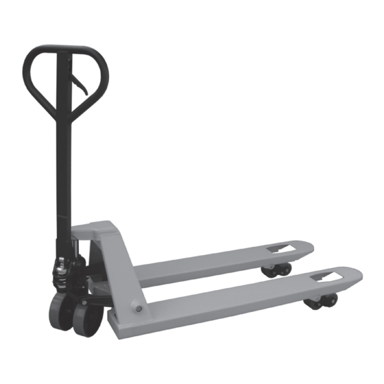
5. Parts description 1. Steering wheels 2. Pump unit 3. Tiller arm 4. Control lever 5. Forks 6. Load wheels 7. Lifting mechanism 8. Swing rod (IM)237‐000413_RHP25_GB-IM_V4_150626.indd 8 7/3/15 17:09... - Page 9 5. Parts description a) Safety pin b) Axle c) Roll pin (x2) d) Hinge e) Adjusting screw Hydraulic valve unit g) Small piston rod h) Roller Adjusting bolt Chain (IM)237‐000413_RHP25_GB-IM_V4_150626.indd 9 7/3/15 17:09...
-
Page 10: Scope Of Delivery
6. Scope of delivery 1 pre-assembled chassis with pump unit 1 pre-assembled tiller arm 1 axle 2 roll pins Please check the completeness of the delivery and ensure that all parts are free from any transport-related damage or any damage in general. Please contact the seller from whom you purchased the product should there be any parts missing or damaged. - Page 11 7. Before use 5. Set the control lever (4) to the “lift” position. Raise the swing rod (8) and insert the adjusting bolt (i) into the slot, with one nut each underneath and above the swing rod (8). 6. Move the nuts on the adjusting bolt (i) close to the swing rod (8) so that it cannot fall out of the slot.
-
Page 12: Operation
7. Before use 6. If the forks (5) do not descend when the control lever (4) is in the “lower” position, turn the adjusting screw (e) on the swing rod (8) clockwise until pulling the control lever (4) lowers the forks (5). Check the “neutral” position afterwards. -
Page 13: Troubleshooting
8. Operation 8.4 Lowering 1. Lower the load by carefully shifting the control lever up to the “lower” position. Ensure there are no obstacles below the load. 2. By releasing the control lever, the lowering movement will stop. 3. Be sure there is adequate clearance behind to remove the product from the lowered goods. - Page 14 9. Troubleshooting Problem Possible cause Solution 1. Forks do not 1.1 Low hydraulic fluid 1. Add approved hydraulic elevate, do not leveI or impurities in fluid or change the oil elevate fully or (→ 10.7 Adding elevate slowly hydraulic oil to the pump reservoir) 1.2 Swing rod is out of 2.
-
Page 15: Cleaning, Maintenance And Repair
9. Troubleshooting Problem Possible cause Solution 3. Forks descend 3.1 Oil impurities are 1. Drain and replace without putting preventing the hydraulic fluid with the control lever release valve from approved fluid in the „lower“ fully closing position 3.2 Some hydraulic 2. - Page 16 10. Cleaning, maintenance and repair 6. Waste material like oil, or others must be probably disposed of and recycled according to the national regulation; if necessary, bring it to a recycling company. 7. All bushings and bearings have been lubricated at factory. To increase their life expectancy, regular maintenance is recommended.
-
Page 17: Storage And Transportation
10. Cleaning, maintenance and repair 10.6 Bleeding the hydraulic system Air may find its way into the pump during transportation, tilting or usage on uneven ground. It can result in not elevating forks while pumping in the “lift” position. The air can be removed in the following way: 1. -
Page 18: Hydraulic Diagram
12. Hydraulic diagram Cylinder Valve Tiller Safety valve Valve Pump Valve Oil tank Lever 13. Disposal Used products are recyclable materials and therefore do not belong in ordinary household waste! We would therefore like to ask you to support us in the conservation of resources and the protection of the environment, and hand this product to return sites –... -
Page 19: Warranty
Purchase receipt – Model description/Type/Brand – Describe the fault and problem as detailed as possible In the case of a claim for guarantee or defects, please contact the seller. GWL 8/14 EN RHP25 ENGLISH 150626 -19- (IM)237‐000413_RHP25_GB-IM_V4_150626.indd 19 7/3/15 17:09...
Need help?
Do you have a question about the RHP25 and is the answer not in the manual?
Questions and answers