
Summary of Contents for Aussie Eco Full Inverter EFI Series
- Page 1 Eco Full Inverter Swimming Pool Heat Pump -Installation and Operation Manual- EFI Series Heat Pumps...
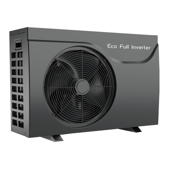
- Page 3 THANK YOU Dear Customer, Thank you for choosing our products and greatly we appreciate your confidence in Full Inverter These are the ECO Swimming Pool Heat Pumps for heating or cooling your pool and extending your swimming season. This is a special Pool heat pumps which has been designed to be as Eco friendly as possible, using market leading technology and experience.
-
Page 5: Table Of Contents
TABLE OF CONTENT INTRODUCTION ............................. 2 This manual............................2 The unit ..............................2 SAFETY INSTRUCTIONS ........................... 3 ITEMS INSIDE PRODUCT BOX .......................... 5 OVERVIEW OF THE UNIT ..........................6 Unit Dimension ............................6 Explode View ............................7 INSTALLATION ............................... 8 Installation information .......................... -
Page 6: Introduction
INTRODUCTION This manual This manual includes the necessary information about the unit. Please read this manual carefully before you use and maintain the unit. The unit The swimming pool heat pump is one of the most economical systems to heat the swimming pool efficiently. -
Page 7: Safety Instructions
SAFETY INSTRUCTIONS To prevent injury to the user, other people, or property damage, the following instructions must be followed. Incorrect operation due to ignoring of instructions may cause harm or damage. Install the unit only when it complies with local regulations, by-laws and standards. Check the main voltage and frequency. - Page 8 Do not install the unit in a place where there is a chance of flammable gas leaks. If there is a gas leak and gas accumulates in the area surrounding the unit, it could cause an explosion. Perform the drainage/piping work according to the installation instruction. If there is a defect in the drainage/piping work, water could leak from the unit and household goods could get wet and be damaged.
-
Page 9: Items Inside Product Box
ITEMS INSIDE PRODUCT BOX Before starting the installation, please make sure that all parts are found inside the box. The Unit Box Item Image Quantity Eco Full Inverter Swimming pool heat pump Installation and Operation Manual Barrel Unions (40mm) Winter Cover Rubber foots for anti-vibration Water Drainage Pipe... -
Page 10: Overview Of The Unit
OVERVIEW OF THE UNIT Unit Dimension MODEL EFI 17 EFI 23 EFI 14 1076... -
Page 11: Explode View
Explode View Name Name Top Cover Reactance Electric box cover Bottom Panel component Support frame Inverter compressor Electronic control components High-pressure valve Fin heat exchanger Low-pressure switch Left panel Power waterproof cover Motor bracket Needle valve DC fan motor Controller Middle panel Four-way valve Right panel... -
Page 12: Installation
INSTALLATION Installation information The following information given here is not an instruction, but simply meant to give the user a better understanding of the installation. Condition of installation The following information given here is not an instruction, but simply meant to give the user a better understanding of the installation. - Page 13 To channel condensation flows, we recommend that you install our condensate drain kit. For this purpose the heat pump must be raised by at least 10 cm. How to install the condensate drain kit? 1. Install your heat pump by raising it by at least 10 cm using solid, moisture-resistant studs. 2.
-
Page 14: Electrical Connection
Electrical connection Electrical supply must correspond to that indicated on the appliance. Unit must be earthed Wiring must be completed by a licensed electrician Set leakage protector according to local code Connection cables have to be sized according to appliance power and installation requirements. Please refer to below table: Cable size Heat pump... -
Page 15: Operating The Unit
After connecting water to the pool system, complete with a suitable by-pass and electrical connections by a qualified electrician. Be sure that: 1) Appliance is horizontal and on a firm base. 2) Water circuit is well connected (no leaks) 3) Electrical circuit is well connected (all cables tightened correctly at terminals and intermediate circuit breaker), insulated and earthed correctly. -
Page 16: Controller Instruction
Controller Instruction General Input Voltage:DC12V RS485 Communication Short-Press for 1~5seconds,Long-Press for 5 seconds. No Button press for more than 30s,controller surface will exit to original normal. User can operate the controller only when the creen is light on. Back light of Screen is orange,characters and symbols are black. Operation temperature range for controller is -30~70℃。... -
Page 17: Instruction For Function
Intructions for Display Symbols :Heating Pool mode :Cooling Pool mode : Auto run mode :Boost run mode :Smart run mode :Silent run mode :Heat Pump output capacity in actual time :wifi function :Water in Temperature :Water out Temperature :Error Warning Instruction for special display When turn off the heat pump,screen only shows the last running symbol and data... -
Page 18: Function Diagnosis
When on status of Parameter Setting , display two“88”,it is asking you to enter your password, press to select, press to confirm.When password is right, displays Parameter No. Displays related parameter value. When on status of Debugging , displays the Number, 01 water pump debugging, 02 testing mode, and displays ON or Off. -
Page 19: Parameter Checking And Adustment
PARAMETER CHECKING AND ADUSTMENT Parameter list Some parameters can be checked and adjusted by the controller. Below is the parameter list. Name Instruction Compressor running Frequency Current hz EEV Open degree Current Value/5 ℃ Current Ambient Temperature ℃ Current Outlet Water Temp. ℃... - Page 20 1.Lack of gas; 1.Check if gas system is leaking; 1.Amend the leakage 2.Refrigerant system block pressure 2.Check if filter is blocked; ; reinject the gas; protection 3.Check ambient Temp. and water temp. 2.change a new filter. 3.Exceed heat pump is over limitation. operation range.
- Page 21 reserved reserved reserved reserved main cable voltage exra low main cable voltage exra high current protection (input side) module abnormity PFC abnormity Compressor start failure Compressor lack-phase IPM module reset Compressor over-current module extra high temperature Current detection Circuit failure out of step Wiring eror or IPM moudule invalid Check if wiring error Re-connect cable or change IPMmudule...
-
Page 22: Maintenance The Unit
limits Failure motor drive MAINTENANCE THE UNIT To protect the paintwork, avoid leaning or putting objects on the device. External heat pump parts can be wiped with a damp cloth and domestic cleaner. (Attention: Never use cleaning agents containing sand, soda, acid or chloride as these can damage the surfaces.) To prevent faults due to sediments in the titanium heat exchanger of the heat pump, ensure that the heat exchanger cannot be contaminated (water treatment and filter system necessary). -
Page 23: Troubleshooting
TROUBLESHOOTING This section provides useful information for diagnosing and correcting certain troubles which may occur. Before starting the troubleshooting procedure, carry out a thorough visual inspection of the unit and look for obvious defects such as loose connections or defective wiring. Before contacting your local dealer, read this chapter carefully, it will save you time and money. -
Page 24: Disposal Requirements
DISPOSAL REQUIREMENTS Dismantling of the unit, treatment of the refrigerant, of oil and of other parts must be done in accordance with relevant local and national legislation. Your product is marked with this symbol. This means that electrical and electronic products shall not be mixed with unsorted household waste. -
Page 25: Wiring Diagram
WIRING DIAGRAM Please refer to the wiring diagram on the electric box. Model: EFI 14/17/23... -
Page 26: Specification
Specification Model EFI 14 EFI 17 EFI 23 Heating Capacity (kW) 14.3 17.4 23.2 Advised Pool Volume (m3) 30-50 40-60 60 -80 Working Air Temp -7℃ ~ 43℃ Performance Condition Air 26℃ Water 26℃, Humidty 80% Heating Capacity (kW) 14.3 17.4 23.2 C.O.P... -
Page 27: Environmental Information
Recycling ENVIRONMENTAL INFORMATION This equipment contains fluorinated greenhouse gases covered by the Kyoto Protocol. It should only be serviced or dismantled by professional trained personnel. This equipment contains R32 refrigerant in the amount as stated in the specification. Do not vent R32A into the atmosphere: R32, is a fluorinated greenhouse gas with a Global Warming Potential (GWP) = 2088. -
Page 29: User Manual For App
User Manual for APP Application – EFI Full Inverter Series... - Page 30 CONTENT ..........................27 Download the APP ............................. 28 Register ......................... 29 Configuration of APP ..........................33 Operation of APP PLEASE DO NOT THROW IT AWAY. KEEP IT IN YOUR FILES FOR FUTURE REFERENCE.
-
Page 31: Download The App
Download the APP Method 1 Android system: Scan the QR code through Browser of Android system. Download the APP and install it. ISO system: Scan the QR code to download the APP and install it. Method 2 Android system: Please browse the internet site http:/47.254.152.109:8080/scadaiot/downFile/execute.do with Browser of Android system to download the APP and install it. -
Page 32: Register
Register Please confirm mobile is already connected to the valid Wi-Fi. Open the APP. Please press Register to sign up first time. Type your email address, and press Next. -
Page 33: Configuration Of App
Please input all the items including Email address, Username, Password and Password confirm, and press Finish for sign-up. After sign up successfully, the interface will change to Log in interface automatically. Notes: The password should be only combined with alphabet and numbers. Configuration of APP Input Email address or Username, password and press Sign in button. - Page 34 Press button Connect heat pump, and the interface will be change to next interface. According to the introduction in the interface, please operate. After the heat pump unit setting, please press Next.
- Page 35 Please in this interface, select your router in your home LAN. Input your router’s password, and please click Binding and Next.
- Page 36 In this interface, first, please give your heat pump names as you want. Press the button click here to set Wi-Fi. For Android system, the interface will directly skip to setting menu of mobile to select HF-LPB130. For ISO system, please manually enter the setting menu of mobile to select HF-LPB130. Till now, the connection is finished between mobile and heat pump unit successfully;...
-
Page 37: Operation Of App
Operation of APP Main icons and functions Setting button Operating mode and function icon Setting temperature icon Ambient temperature Temperature setting bar Mode setting button Inquire button Fault button Function setting button On/Off button Add heat pump unit button Refresh button... - Page 38 Button introductions Setting Press Setting button, the interface will be changed to setting interface as following picture. Through this interface, a. The name of heat pump unit which is connected with your mobile APP can be changed. b. Delete heat pump unit which is already added in your APP. c.
- Page 39 After set the operating mode, in the icon area of mode will display your selection in the left side of the screen. Cooling mode Heating mode Auto mode Function setting button This button is used to select the operating function which includes boost, smart and silence mode.
- Page 40 After set the function mode, in the icon area of mode will display your selection in the left side of the screen. Silence mode Smart mode Boost mode Inquire button Press Inquire button, the inquire interface will be displayed. From this interface, the following current parameter of the heat pump unit will be displayed.
- Page 41 Fault button Press Fault button, and the fault records include history and current error or protection codes will be displayed.
- Page 42 Add heat pump unit Press this button, and the interface will be changed to add new unit interface as the following picture. Please repeat previous introduction finish the following steps. Refresh button Press this button, the displayed current setting temperature and ambient temperature in screen will be refreshed.
- Page 43 Tips: 1. If the heat pump unit is already set with Android or ISO system, you want to change ISO or Android system mobile phone, and please following steps: a. Press the adjustment buttons ( ) of heat pump controller at the same time till you hear the prompt sound.
- Page 44 Australian Energy Systems Unit 17/6 Maunder St Slacks Creek Queensland 4127 Phone: 07 3299 2700 Web: www.poolheating.com.au Email: reception@poolheating.com.au...
Need help?
Do you have a question about the Eco Full Inverter EFI Series and is the answer not in the manual?
Questions and answers