Advertisement
Quick Links
VLF-3 Rev #1C Assembly Instructions
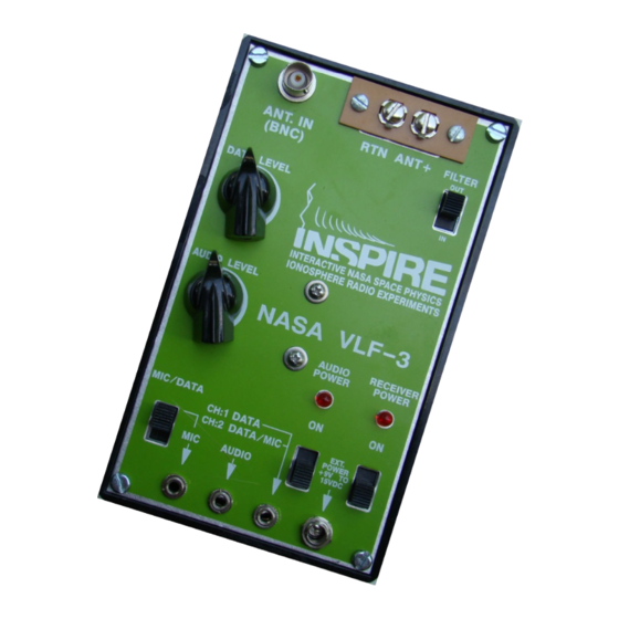
INSPIRE VLF-3 Rev #1C Receiver Kit
ASSEMBLY INSTRUCTIONS
The following assembly instructions should be followed carefully. The INSPIRE VLF-3
receiver kit is NOT a simple electronic assembly. If you follow the instructions carefully
you should be successful in building a receiver that works. If you are not careful, you
run the risk of having a problem that is very difficult to locate and fix.
TOOLS NEEDED:
Philips head screwdriver
Small standard screwdriver
Wire cutters
Wire stripper
Soldering iron (15-25 watt, small tip)
Light duty resin core solder (60/40)
Sponge
Magnifying glass
Solder sucker or solder wick
1
Advertisement

Related Manuals for Inspire VLF-3

Summary of Contents for Inspire VLF-3
- Page 1 INSPIRE VLF-3 Rev #1C Receiver Kit ASSEMBLY INSTRUCTIONS The following assembly instructions should be followed carefully. The INSPIRE VLF-3 receiver kit is NOT a simple electronic assembly. If you follow the instructions carefully you should be successful in building a receiver that works. If you are not careful, you run the risk of having a problem that is very difficult to locate and fix.
- Page 2 VLF-3 Rev #1C Assembly Instructions KIT CONTENTS: 1. Black plastic enclosure 2. Face Plate 3. Printed Circuit Board (PCB) 4. Four bags of components: Bag 1 resistors, inductors Bag 2 capacitors Bag 3 ICs, diodes, sockets Bag 4 switches, jacks, knobs, antenna terminal, wires, miscellaneous hardware...
- Page 3 VLF-3 Rev #1C Assembly Instructions Faceplate Front Control Panel Printed Circuit Board (PCB): Component Side / Battery Side Switch Side All electronic components are The four DPDT slide switches, the inserted from this side and soldered two 10k pots and the two LEDs on the other side.
- Page 5 VLF-3 Rev #1C Assembly Instructions Instructions Outline 1. Solder components to the Printed Circuit Board (PCB) 2. Connect wires to PCB 3. Install jacks and connectors to the faceplate 4. Attach the PCB to the faceplate 5. Solder wires to jacks and 6.
- Page 6 1. SOLDER COMPONENTS TO Printed Circuit Board (PCB) These instructions refer to assembling the INSPIRE VLF3 receiver kit with the PCB marked on the edge as “NASA VLF-3 REV #1C”. A few things need to be noted before you begin assembly.
- Page 7 VLF-3 Rev #1C Assembly Instructions 5) Let’s take some time to talk about soldering. If you are comfortable with soldering, skip along to the next section and have at it. If not, let’s start with a brief overview of how to solder.
- Page 8 VLF-3 Rev #1C Assembly Instructions...
- Page 9 VLF-3 Rev #1C Assembly Instructions IMPORTANT Note for New Soldering Irons: A new soldering iron must be “tinned” in order to work well. Follow these steps: 1. Plug in the iron. 2. When it first heats up, apply solder liberally to the tip.
- Page 10 VLF-3 Rev #1C Assembly Instructions 1a. Sort and Install Resistors Remove the resistors from Bag 1. Leave the inductors for later installation. The colored bands on the resistors indicate the Bag 1 Contents resistance using a color code. This table indicates Resistors: how to convert each color to its numerical equivalent.
- Page 11 VLF-3 Rev #1C Assembly Instructions Care should be used in identifying R3 (2.2 MegΩ) and R4 (22 MegΩ). The green band and the blue band can look similar. For best results, identify both components together so differences can be noted.
- Page 12 VLF-3 Rev #1C Assembly Instructions After installing the resistors you will have something like the following picture. The capacitors, inductors, and diodes are installed in the same way.
- Page 13 VLF-3 Rev #1C Assembly Instructions 1b. Install the IC sockets Remove the IC sockets and IC1 (LM386) and IC2 (LM358) from Bag #3. When installing IC sockets and ICs, alignment is very important. One end of the IC symbol on the PCB has a half-hole at one end of the symbol.
- Page 14 VLF-3 Rev #1C Assembly Instructions 1c. Solder capacitors to the PCB Capacitor Identification Guide The small-value ceramic capacitors may be installed Bag #2 Contents in either orientation, but the larger-value cylindrical capacitors (C4, C8, C10, C14, C16, C18, C19) must Capacitors: be installed with the proper polarity.
- Page 15 VLF-3 Rev #1C Assembly Instructions 1d. Install the inductors (L1 and L2) The inductors are the two remaining parts in Bag #1. Inductor L1 is marked “LH 239”. Inductor L2 is marked “LJ 415”. From the component side, press the inductor firmly down against the PCB and solder the other side.
- Page 16 VLF-3 Rev #1C Assembly Instructions 1f. Install the battery holder From Bag #4, take the following parts: 1 Battery holder 2 PCB standoff post 2 4-40 3/8 “ screw 4 4-40 1/4” screw 2 4-40 nuts 2 nylon washers 2 #4 washers 1.
- Page 17 VLF-3 Rev #1C Assembly Instructions 1g. Install the potentiometer and switches From Bag #4, remove the two 10k pots (R7 and R26) and the four Double Pole Double Throw (DPDT) slide switches. Slide the three contacts for the pots through the holes provided from the switch side of the PCB (non-component side).
- Page 18 VLF-3 Rev #1C Assembly Instructions 2. ATTACH WIRES TO THE PCB Bag #4 contains the following wires: 3” red 4” orange 4” yellow 3” blue 3” black 5” white Cut each color wire to produce the following lengths (the blue wire is not cut): 1 red: 1”, 2”...
- Page 19 VLF-3 Rev #1C Assembly Instructions Wires installed (component-side view) Close up of white and black wire twisted together prior to being soldered to location #2 on the PCB Wires installed (switch-side view)
- Page 20 VLF-3 Rev #1C Assembly Instructions 3. INSTALL THE JACKS AND CONNECTORS TO THE FACEPLATE Install the jacks and the external power connector to the faceplate by inserting them from the back side and tightening the knurled nut on the front side. Mount the 2-screw antenna terminal to the faceplate by placing the terminal in front of the faceplate and using the two remaining 4-40 1/4”...
- Page 21 VLF-3 Rev #1C Assembly Instructions Close-up showing wires soldered to the jack tabs NOTE: The orange and yellow wires must cross to connect to the appropriate jacks. Solder the black “RTN” wire to the RTN side of the antenna terminal.
- Page 22 VLF-3 Rev #1C Assembly Instructions THIS COMPLETES THE ASSEMBLY OF YOUR VLF-3 RECEIVER 6. TEST YOUR RECEIVER Attach an antenna to the ANT+ terminal – a 1-2 meter piece of wire will do. Attach a ground to the RTN terminal – a short wire that you hold in your hand will do.
- Page 23 VLF-3 Rev #1C Assembly Instructions 6a. Test the audio output Plug some headphones in the audio output jack. Turn on the “RECEIVER POWER” switch (main power switch). Turn on the “AUDIO POWER” switch and slowly turn the “AUDIO LEVEL” up.
- Page 24 If you hear hum, if the hum gets louder when you touch the antenna terminal, then your VLF-3 receiver seems to work. Take it into the field well away from power lines, connect the RTN to the metal of your car or to a solid ground stake, connect the ANT+ to an antenna or connect a whip antenna to the BNC connector, and listen again as you turn up the volume.
- Page 25 CustomerService@TheINSPIREProject.org Any corrections, suggestions or recommendations for improvement of the assembly instructions would also be appreciated. If you would like to submit an article on field observations to The INSPIRE Journal, please email: Editor@TheINSPIREProject.org Thank you for your participation and support of The INSPIRE Project!
Need help?
Do you have a question about the VLF-3 and is the answer not in the manual?
Questions and answers