Table of Contents
Advertisement
Quick Links
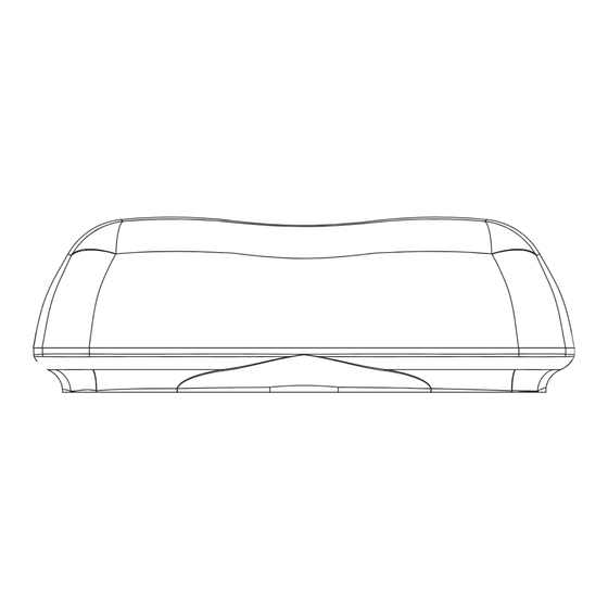
BF920 Series
LED Twin Beacon
Introduction
The BF920 is a weatherproof LED based warning light beacon, that contains two
state-of-the-art high intensity BF900 beacons, in a sealed housing with alloy metal base.
WARNING!
This product contains high intensity LED devices. To prevent eye damage,
DO NOT stare into light beam at close range.
WARNING!
The use of this or any warning device does not insure that all drivers can or
will observe or react to an emergency warning signal. Never take the right-
of-way for granted. It is your responsibility to be sure you can proceed safely
before entering an intersection, driving against traffic, responding at a high
rate of speed, or walking on or around traffic lanes.
The effectiveness of this warning device is highly dependant upon correct
mounting and wiring. Read and follow the manufacturer's instructions
before installing or using this device. The vehicle operator should insure daily
that all features of the device operate correctly. In use, the vehicle operator
should insure the projection of the warning signal is not blocked by vehicle
components (i.e. open trunks or compartment doors), people, vehicles,
or other obstructions. This equipment is intended for use by authorised
personnel only. It is the user's responsibility to understand and obey all laws
regarding emergency warning devices. The user should check all applicable
city, state and federal laws and regulations.
Britax assumes no liability for any loss resulting from the use of this
warning device. Proper installation is vital to the performance of this warning
device and the safe operation of the emergency vehicle. It is important to
recognise that the operator of the emergency vehicle is under psychological
and physiological stress caused by the emergency situation. The warning
device should be installed in such a manner as to: a) not reduce the output
performance of the system, b) place the controls within convenient reach
of the operator so that he/she can operate the system without losing eye
contact with the roadway.
Emergency warning devices often require high electrical voltages and/or
currents. Properly protect and use caution around live electrical connections.
Grounding or shorting of electrical connections can cause high current arcing,
which can cause personal injury and/or severe vehicle damage, including fire.
PROPER INSTALLATION COMBINED WITH OPERATOR TRAINING IN THE
PROPER uSE OF EMERGENCY WARNING DEVICES IS ESSENTIAL TO INSuRE
THE SAFETY OF EMERGENCY PERSONNEL AND THE PuBLIC.
Features and Specifications
Operating Voltage:
DC10V-30V, Reverse Polarity Protected
Lens:
Polycarbonate (Clear and amber option)
Base:
Aluminium alloy
Optics:
SAE J845 Class 1 compliance
Electromagnetic:
ISO 13766:2006
Environment:
Temperature -30⁰C to +50⁰C
Maintenance:
The beacons are completely sealed units designed to be maintenance free.
There are no repairable parts inside.
INSTALLATION & OPERATION MANUAL
Read all instructions and warnings before installing and using.
This manual must be delivered to the end user of this equipment.
Compliance Data for each BF900
Vibration test:
SAE J845
Electromagnetic:
ISO 13766:2006
Mechanical Tests: SAE J575
• Vibration
• Moisture
• Dust
• Corrosion
• Warpage
Photometry Tests: SAE J845
• P hotometric Classifications (Amber and Clear Lens)
• Flash rate
Colour Test:
SAE J578
• Amber beacon
Environment:
SAE J845
• High temperature +50⁰C
• Durability
In addition to SAE J845 testing BF900 series also complies
to the following EMC and ESD standard:
EMC: ISO13766
• B road band Electromagnetic Emissions 30Mhz-1Ghz
• N arrow band Electromagnetic Emissions 30Mhz-1Ghz
• I mmunity of ESA to electromagnetic radiation
ISO11452-4, ISO11452-2
• E lectrostatic Discharge (ESD) ISO10605
• E mission of conducted disturbances ISO 7637-2
Flash Patterns
Factory preset mode patterns
MODE
PATTERN NO.
Default
PA5
1
PA6
2
PA2
3
PA3
There are seven other flash pattern options
PATTERN NO. DESCRIPTION
SYN
PA0
Auto or random
No
PA1
Single Flash 2.5Hz
Yes
PA2
Rotator 150rpm
No
PA3
Double Flash 2.5Hz
Yes
PA4
Rotator 210rpm
No
PA5
Quad Flash 2.5Hz
Yes
PA6
Single Flash 3.5Hz
Yes
Please note that the flash pattern change switch is located inside inner beacon lens.
Current Draw
Maximum Current Draw: Imax = 5A @ 12.8V (single flash)
DESCRIPTION
Quad Flash 2.5Hz
Single Flash 3.5Hz, Fast
Rotator 150rpm
Double Flash 2.5Hz
ALT
Comments
No
All switches OFF
Yes
SWITCH 1 ON
Yes
SWITCH 2 ON
Yes
SWITCH 3 ON
Yes
SWITCH 4 ON
Yes
SWITCH 5 ON
Yes
SWITCH 6 ON, Fast Flash
Advertisement
Table of Contents

Related Manuals for Britax BF920 Series

Summary of Contents for Britax BF920 Series
- Page 1 Flash Patterns Britax assumes no liability for any loss resulting from the use of this warning device. Proper installation is vital to the performance of this warning Factory preset mode patterns device and the safe operation of the emergency vehicle. It is important to recognise that the operator of the emergency vehicle is under psychological and physiological stress caused by the emergency situation.
- Page 2 Britax Automotive Equipment shall in no way be liable for other Remove lens and select most suitable mounting points in alloy base (as per above).
Need help?
Do you have a question about the BF920 Series and is the answer not in the manual?
Questions and answers