Table of Contents
Advertisement
Quick Links
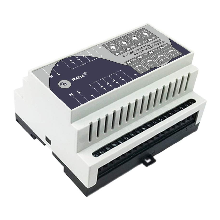
HASEMAN ELECTRIC
R4D4
USER MANUAL
Haseman R4D4 combines 4 relay outputs and 4
powerful universal dimmers (user selectable Leading /
Trailing Edge), produced by using of Z-Wave Plus, the
latest version of Z-Wave.
WHAT IS Z-WAVE?
Z-Wave is international standard protocol for wireless
communication in smart homes and buildings.
Z-Wave enables smart home products to talk to each
other. This creates the backbone of your smart home
and enables you to use your smartphone or tablet to
create one-touch scenes that help with daily activities
like: saving energy, keeping your home secure and
being more comfortable.
Z-Wave
technology
is
simple:
each
transmitted
message is reconfirmed (2-way communication) and
every mains powered device can act as a repeater for
other devices (mesh network). The more Z-Wave
products you have in your smart home, the stronger
your smart home network is.
Z-Wave technology is the leading solution in smart
home automation. There is a wide range of Z-Wave
devices that are fully compatible, independently of the
manufacturer. It gives the system the ability to evolve
and expand over time.
SAFETY INFORMATION
Read this manual before attempting to install the
device! Failure to observe recommendations included in
this manual may be dangerous or cause a violation of
the law.
The manufacturer will not be held responsible for any
loss or damage resulting from not following the
instructions of operating manual.
DANGER OF ELECTROCUTION!
All works on the device may be performed only
by a qualified and licensed electrician. Observe
national regulations.
The device is designed to operate in electrical home
installation. Faulty connection or use may result in fire
or electric shock.
Even when the device is turned off, voltage may be
present at its terminals.
Any
maintenance
introducing
changes
configuration of connections or the load must be
always performed with disabled fuse.
CONNECTION DIAGRAMS
When connecting the module, observe the
proper Neutral (N) and Line (L) terminals.
Each relay channel has its own Input (In) and
Output
(O),
which
allows
controlling
devices, supplied by different voltages (12,
24, 48VDC / VAC, 110-240 VAC, etc.)
During operation, each channel status
is indicated by a panel indication LED.
INSTALLATION
Mount the module on standard DIN Rail.
Connect the local control lines S1 to S8 (if local
control is used). Depending on the BUTTON TYPE
Parameter (separate for each Channel), Push Buttons
or Toggle Switches can be connected:
Only Voltage Free contacts must be connected
between terminal Com and terminals S1 to S8.
Connect the controlled lines. Depending on the load
type (Dimmable or On-Off), load power and supply
voltage, use one of the following connection diagrams.
into
the
DIMMER OUTPUTS (CH. 1 – CH. 4):
For dimmable lights up to 500W per channel:
For dimmable lights up to 300W per channel:
of
RELAY OUTPUTS (CH. 5 – CH. 8):
For 230V On/Off controllable loads:
For low voltage AC/DC loads:
For On/Off controllable loads with current
consumption more than 10 Amps:
When necessary, the dimmer channels (CH.1
to 4) can also be used to control not
dimmable
loads
in
On/Off
Mode,
configuring the channel as a TRUE SINE (see
Configuration Parameters below).
by
Advertisement
Table of Contents

Summary of Contents for Haseman Electric R4D4
- Page 1 CONNECTION DIAGRAMS When connecting the module, observe the proper Neutral (N) and Line (L) terminals. Haseman R4D4 combines 4 relay outputs and 4 powerful universal dimmers (user selectable Leading / Trailing Edge), produced by using of Z-Wave Plus, the latest version of Z-Wave.
- Page 2 However certain configuration can Routing slave Available Settings: R4D4 also supports Auto Inclusion (by customize its functionality and fit it to your specific This form of Z-Wave slave is one that knows its switching On its power supply, while the Z- project needs.
- Page 3 TRUE SINE MODE (555) Sample configuration screen in Fibaro HC UI: SOFT START (separate for each channel) OVER TEMPERATURE PROTECTION If the MAX LEVEL (parameter 92 to 95) of a dimmer Parameters No: 84 to 87 (for Channel 1 to 4) If the max load of the dimmer channels exceeds the (CH 1 to 4) is set to value 555, such a channel will module rated power, or the ambient temperature in...
- Page 4 Sample view in Fibaro Home Center: ENCLOSURE DIMENSIONS (mm) - Damages caused by operating or storing the device WARRANTY extremely adverse conditions, such high humidity, dust, too low (freezing) or too high ambient We warrant that the device is free from defects in temperature;...
Need help?
Do you have a question about the R4D4 and is the answer not in the manual?
Questions and answers