Advertisement
Quick Links
Advertisement

Related Manuals for GRAYHILL 3D50 Series

Summary of Contents for GRAYHILL 3D50 Series
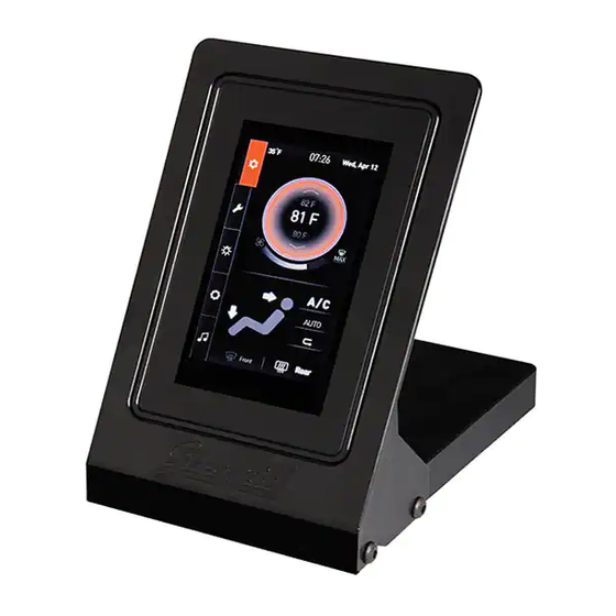
- Page 1 Grayhill 3D50 Series 5 Inch Display Development Kit Hardware Setup Instructions...
-
Page 2: Revision History
Revision History Revision Date Description 12/16/2015 Original Release 03/07/2016 Added USB to CAN adapter to equipment list 04/28/2016 Added Appendix A. 3D50 Development Kit Hardware Setup Instructions... -
Page 3: Hardware Setup Instructions
Ethernet, CAN bus, and RS-232 serial bus. These instructions are applicable to doing software development for the 3D50 Display using either the Qt Development environment or the Grayhill VUI Builder© software. Equipment from Grayhill Included with 3D50Dev-100 Kit 3D50VT-100 Display ... - Page 4 Connect the 18-pin DT cable to . Be Breakout Board sure to match Pin 1 on the cable to Pin 1 on the Breakout Board 4. Connect 18-pin DT cable to back of the 3D50 Display. Note that this connector is keyed.
- Page 5 The Series 3D50 Display device has two CAN bus interfaces that can be used for various purposes. The Grayhill VUI Builder© software communicates with the 3D50 Display via either CAN bus. The VUI Builder© software tool currently supports using a GridConnect USB to CAN adapter which requires adapter software from GridConnect.
- Page 6 Appendix A. POWER REQUIRMENT Voltage: 12V Current: 1.5A J6, J7, J9, J10 J2, J3 TYCO PJ-002AH RCJ-014-SMT 747844-6 J1 MAIN CONNECTOR Mating Connector HOUSING: DEUTSCH DT16-18-SA-K004 TERMINAL: DEUTSCH 0462-201-16141 SCHEMATIC 3D50 Development Kit Hardware Setup Instructions...
- Page 7 MAIN CONNECTOR (J1) POWER SWITCHES VBAT (SW1) and VSW (SW2) 3D50 Development Kit Hardware Setup Instructions...
- Page 8 VIDEO INPUTS CAM1 (J2) and CAM2 (J3) CAN CONNECTORS CAN1 (J6) and CAN2 (J7) RS232 CONNECTOR COM1 (J9) IO CONNECTOR I/O1 (J10) 3D50 Development Kit Hardware Setup Instructions...
- Page 9 DIP Switch SW3 Leave both switches open (OFF) for normal operation. Closing both switches (ON) connects CAN port 1 to CAN port 2. DIP Switch SW4 Leave all switches open (OFF) for normal operation. Closing switch 1 (ON) connects DIG_IN_1 to IO1 Closing switch 2 (ON) connects IO2 to IO1 Closing switch 3 (ON) connects IO2 to IO3 Closing switch 4 (ON) connects IO4 to IO3...
- Page 10 LEDs D2,D3,D4, D5, and D6 LEDs are illuminated if their corresponding signal is high. 3D50 Development Kit Hardware Setup Instructions...
Need help?
Do you have a question about the 3D50 Series and is the answer not in the manual?
Questions and answers