Advertisement
Quick Links
Advertisement

Summary of Contents for IntelliSense EDS-18P
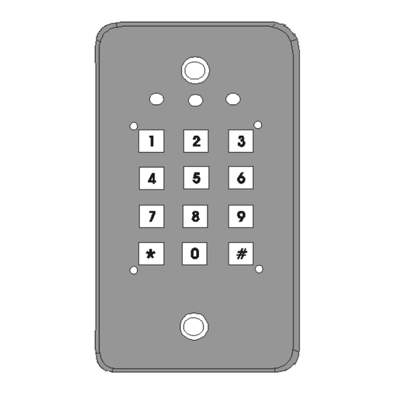
- Page 2 The EDS – 18P is designed for door strike applications and remote control of a security control panel. Features ........Microprocessor controlled.
-
Page 3: Security Codes
Operation ....... . . 2.1 Security Codes USER CODE 1 - activates the Key Relay. - Page 4 2.3 Activate the Key Relay Either (a) or (b): (a) Enter User Code 1 (default value 2 2 2 2); (b) Press the remote control button (Section 2.8) 2.4 Activate the Auxiliary Relay Enter User Code 2 (default value 2 2 2 2). 2.5 Activate BOTH the Key &...
- Page 5 2.7 Restore the Master Code If the Master Code is forgotten, the user can still restore the Master Code to its default value of 1 2 3 4. To do that (1) Disconnect the power supply. (2) Move the restore jumper from NORMAL to RESTORE position (Figure 4.1).
- Page 6 (Page 8 of original manual) Programming......Procedures (1) Enter Master Code (default value 1 2 3 4). (2) Enter the * Key.
- Page 7 (Page 9 of the original manual) Table 3.1 : Programmable Functions of the EDS - 18 Default Access Key Function Allowed Values Value Master Code 1 2 3 4 0000 - 9999 User Code 1 1 1 1 1 0000 – 9999 except Master Code 0000 –...
- Page 8 Default Access Key Function Allowed Values Value 0000 Disable Panic Key Enable 0000 Enable 0001 No safety level set. 0000 After 4 successive 0001 wrong codes, stay idle 30 sec. After 4 successive 0002 wrong codes, stay idle 60 sec. Security Level 0001 After 4 successive...
-
Page 9: Power Requirements
(page 12 of the original manual) Installation......Surface Mounting Procedures : (1) Use the mounting box as a template to mark holes for the 2 mounting screws. - Page 10 Page 14 of the original manual Power Input (TB1-1, TB1-2) A 10 – 15 volt dc should be connected to these 2 terminals. Tamper Switch (TB1-3, TB1-4) The tamper switch is normally closed. It will be opened when one attempts to open the keypad.
- Page 11 (Page 16 of the original manual) Specifications of the EDS – 18P Operational Voltage Range: 10 – 15V dc Normal – 10mA Key Relay on – 42mA Current consumption (nominal): Auxiliary Relay on – 27mA Both Relays on – 58mA 24V dc, 5A maximum Key Relay contact ratings: 120V ac, 5A maximum...
-
Page 14: Important Notice
IMPORTANT NOTICE READ THE FOLLOWING INSTRUCTIONS IF YOU WANT TO CONNECT AN ELECTRIC DOOR LOCK TO EITHER RELAY OF THE EDS – 18P. An electric door lock is essentially a solenoid controlled door strike. When the lock is turned on/off, electromagnetic induction causes noise and transient voltage to be generated which can feedback into the EDS 18P and cause damage. - Page 15 IF YOU USE AN AC POWER SUPPLY Connect a 18Vrms varistor CLOSE to the door lock in parallel, as shown in Figure A2. Beware that the AC supply voltage cannot exceed the varistor voltage. If your door lock needs an AC voltage higher than 18Vrms, use a varistor with a higher voltage.

Need help?
Do you have a question about the EDS-18P and is the answer not in the manual?
Questions and answers