Table of Contents
Advertisement
Quick Links
Advertisement
Table of Contents

Summary of Contents for Anderson SMARTMIX ST Series
- Page 1 404623 Mixer SMARTMIX Operator's Manual ORIGINAL NOTICE – 2019...
-
Page 5: Table Of Contents
Table of contents How to reach us Starting guidelines Anderson limited warranty About this manual Introduction 1.1 Overview 1.2 Technical specifications 1.3 Optional parts 1.4 Machine identification 1.5 Safety and operating pictograms Safety precautions 2.1 Basic safety guidelines 2.2 Safety tips for transport 2.3 Safety tips for hitching... - Page 6 7.8 Sharpening or replacing the knives 7.9 Adjusting or replacing the auger scrapers 7.10 Checking and adjusting the conveyor tension 7.11 Checking and adjusting the scrapers 7.12 Maintaining the jacks 7.13 Tightening torque 7.14 Cleaning 7.15 Storage Operator's Manual – Mixer Anderson Group...
-
Page 7: How To Reach Us
Please always call your representative first. If your representative is absent or helping another customer, our support team can provide immediate assistance. Anderson service department works in partnership with your dealer. Together, we will ensure any problems you encounter are resolved quickly and efficiently. -
Page 9: Starting Guidelines
Starting guidelines Before starting your Anderson equipment, we strongly recommend that you: Carefully read and understand the contents of this manual Follow all safety guidelines Follow the start-up procedures NOTE: This manual contains important information about equipment maintenance and use. Please give it to the new owner when selling or transferring it. -
Page 11: Anderson Limited Warranty
The one-year warranty begins on the date the new equipment is sold to the customer. If during the year following the purchase of a new equipment, your Anderson equipment fails to function properly due to defective design, materials, manufacturing or assembly, our company will repair your equipment free of charge. - Page 12 Except for conditions or warranties which may not be excluded by law, the selling dealer makes no warranty of its own on any item warranted by Anderson unless it delivers to the purchaser a separate written warranty document specifically warranting the item. The selling dealer has no authority to make any representation or promise on behalf of Anderson or to modify the terms or limitations of this warranty in any way.
-
Page 13: About This Manual
This guide covers all SMARTMIX mixer models. Ensure that you consult the sections that apply to your machine. Disclaimer The illustrations and information in this manual are accurate as of printing. Anderson Group reserves the right to modify its machines without prior notice. Conventions “Danger!”... -
Page 15: Introduction
1 Introduction Congratulations! You have just purchased an Anderson SMARTMIX mixer, which is a quality piece of machinery specially designed for feeding herds. The mixer: Stores silage, supplements and all types of bales; Mixes, and if necessary, cuts these different products;... -
Page 16: Overview
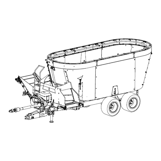
1.1 Overview The following figures show the main components of SMARTMIX mixers. Figure 1 — Main Components of the SMARTMIX Mixer Figure 2 — Main Components of the SMARTMIX Mixer (continued) Operator's Manual – Mixer Anderson Group... - Page 17 Figure 3 — SMARTMIX Auger Anderson Group Mixer – Operator's Manual...
-
Page 18: Technical Specifications
1.2 Technical specifications NOTE: SMARTMIX ST models are equipped with a side hatch, and SMARTMIX FD models are equipped with a front horizontal conveyor. 1.2.1 SMARTMIX ST Figure 4 — Dimensions: SMARTMIX ST Operator's Manual – Mixer Anderson Group... - Page 19 Width at wheels 2.17 m (7 2.06 m (6 2.46 m (8 2.46 m (8 ft. 1 in.) ft. 9 in.) ft. 1 in.) ft. 1 in.) No capacity extension Anderson Group Mixer – Operator's Manual...
- Page 20 Optional 10.4 13.8 m (490 18.8 m (666 ft. 25.4 m (897 ft. 45 cm (18 (367 ft. in.) capa- city exten- sion PTO speed 540 or 1,000 rpm Operator's Manual – Mixer Anderson Group...
- Page 21 40 km/h (25 mph) speed Tires 15.0/55-17 15.0/55-17 26 385/65R22.5 L 275/70R22.5 26 PLY (double) Tire inflation pressure 7.1 bar (103 7.1 bar (103 8.9 bar (130 psi) 9 bar (130 psi) psi) psi) Two-speed gearbox option Anderson Group Mixer – Operator's Manual...
- Page 22 1.2.2 SMARTMIX FD Figure 5 – Dimensions: SMARTMIX FD Operator's Manual – Mixer Anderson Group...
- Page 23 3.47 m (11 3.52 3.37 3.53 1.2 m (4 (11 ft. 6 ft. 4 in.) (11 ft. 7 (11 ft. 1 (11 ft. 7 ft.) inclined in.) in.) in.) in.) conveyor in operation No capacity extension Anderson Group Mixer – Operator's Manual...
- Page 24 1.30 m (4 1.43 m (4 1.67 m (5 1.89 m (6 1.87 m (6 1.5 m (5 ft. 3 in.) ft. 8 in.) ft. 6 in.) ft. 2 in.) ft. 2 in.) ft.) inclined conveyor Operator's Manual – Mixer Anderson Group...
- Page 25 25.4 m (897 34.3 44.6 (490 ft. (1,212 ft. (1,575 ft. cm (18 in.) capa- city exten- sion PTO speed 540 or 540 or 1,000 540 or 1,000 1,000 rpm 1,000 rpm 1,000 rpm Anderson Group Mixer – Operator's Manual...
- Page 26 (13,200 lb.) (17,800 lb.) (25,300 lb.) (28,600 lb.) Load capacity 5,010 6,820 9,550 16,500 16,500 (11,020 lb.) (15,000 lb.) (21,010 lb.) (36,300 lb.) (36,300 lb.) Maximum 40 km/h (25 mph) authorized speed Two-speed gearbox option Operator's Manual – Mixer Anderson Group...
-
Page 27: Optional Parts
SMARTMIX FD models are equipped with a front horizontal conveyor. Table 5 — Optional Parts for SMARTMIX Mixers Optional A280 A380 A380 A520 A520 A700 A700 A950 A1230 parts Rear hatch Magnetic extractor 0.9 m (3 ft.) inclined con- veyor Anderson Group Mixer – Operator's Manual... - Page 28 Total weight repeater screen Direct drive, 540 rpm Two- speed gearbox, 540 Direct drive, 1,000 rpm Two- speed gearbox, 1,000 rpm 3.75 (14.75 in.) offset for the horizontal conveyor Operator's Manual – Mixer Anderson Group...
-
Page 29: Machine Identification
A 5 cm x 10 cm (2 in. x 4 in.) nameplate is located on the right side of the Equipment type (e.g. trailer, blower). It displays the following information about your equipment: Model Serial number Tare weight Gross weight Manufacturing year Anderson Group Mixer – Operator's Manual... -
Page 30: Safety And Operating Pictograms
SMARTMIX mixers have numerous labels that detail the main safety and operating guidelines. Ensure that you see and understand them. Table 6 — Safety and Operating Pictograms Pictogram Meaning Warning! Carefully read and understand the contents of the operator’s manual before using the machine. Operator's Manual – Mixer Anderson Group... - Page 31 See chapter 7 Maintenance. Warning! Risk of fingers and hands being severed. Keep your hands clear of the moving mixing augers. Anderson Group Mixer – Operator's Manual...
- Page 32 Warning! Risk of hands being crushed. Warning! Risk of getting caught in the conveyor belt. Keep clear of the conveyor when it is running. Warning! Strong magnetic field. Individuals with pacemakers must keep clear. Operator's Manual – Mixer Anderson Group...
- Page 33 During work, keep clear of the machine. Warning! Consult the manual before entering the machine. Warning! Crushing hazard. Ensure that the safety valve lever has been rotated 90 degrees before entering the mixing chamber. Anderson Group Mixer – Operator's Manual...
- Page 34 Warning! Do not go underneath the inclined conveyor. It could fall. Warning! Always attach the safety chain before driving on public roads. Maximum authorized rotation speed at the equipment intake. Greasing point. See chapter 7 Maintenance. Operator's Manual – Mixer Anderson Group...
- Page 35 Oil tank. See chapter 7 Main- tenance. Warning! Check that the wheels are tight. See chapter 7 Main- tenance. Recommended oil flow rate. See "Getting started" on page 47. Recommended auger position. See "Getting started" on page Anderson Group Mixer – Operator's Manual...
- Page 36 See "Getting started" on page 47. Low or high speed. Warning! Stop the drive shaft before changing speeds. See "Getting started" on page 47. Operator's Manual – Mixer Anderson Group...
-
Page 37: Safety Precautions
2 Safety precautions Your Anderson Equipment type (e.g. trailer, blower) was designed to minimize risk to the operator. Nevertheless, it must only be used for its intended purpose. Misuse of the Equipment type (e.g. trailer, blower) may result in injury to the operator. - Page 38 Ensure that the warnings and pictograms remain clean and clearly visible. In the event of damage, ask your manufacturer (or dealer) for new labels. During repairs, ensure that any replacement parts bear the same labels as the original parts. Operator's Manual – Mixer Anderson Group...
- Page 39 If you can exit the tractor without touching the electrical cables, jump out without touching the machine and the ground simultaneously. Ensure that nobody touches the machine until the power lines no longer carry a current. Ask for the power line to be disconnected. Anderson Group Mixer – Operator's Manual...
-
Page 40: Safety Tips For Transport
Attach the retaining bars to the transfer panels by putting two plastic hose clamps through the holes in the bars (Figure 7, Detail A and B). Figure 7 — Retaining Bars If your machine has a horizontal conveyor, check that it is centred. Operator's Manual – Mixer Anderson Group... - Page 41 Figure 8 — Inclined Conveyor in Transport Position If the conveyor is lowered while the machine is backing up, it reduces operator visibility and can cause collisions with people or obstacles behind the machine. Anderson Group Mixer – Operator's Manual...
-
Page 42: Safety Tips For Hitching
Do not exceed the maximum load permitted on the hitching points. If necessary, place ballast weights on the supports provided in accordance with the tractor manufacturer’s instructions. When hitching the machine, install all the support and stability equipment to prevent instability. Operator's Manual – Mixer Anderson Group... -
Page 43: Safety Tips For Maintenance And Repairs
Move any combustible materials (hay, organic matter, gasoline, etc.) away from the area before welding. Eliminate any risk of fire. 2.4.3 Electrical Before starting work on the electrical system, disconnect the battery or electrical power supply. Anderson Group Mixer – Operator's Manual... - Page 44 Turn off the engine and remove the key from the ignition. Put the gearshift in neutral and apply the handbrake. Disengage the PTO and uncouple the drive shaft from the PTO. Disconnect the hydraulic supply hoses. Operator's Manual – Mixer Anderson Group...
-
Page 45: Safety Tips For The Pto And Drive Shaft
Disengage the PTO when the drive shaft is likely to reach its maximum angle, especially during turns, climbs and descents. After uncoupling it from the drive shaft, cover the tractor’s PTO with its protective cap. Contact between the drive shaft and the tractor or machine may result in damage. Anderson Group Mixer – Operator's Manual... - Page 46 Carefully follow the safety instructions from the drive shaft manufacturer. For drive shaft maintenance, see its technical manual. The guards must be anchored to the machine and the tractor. If the shear bolt or guards are damaged, immediately replace them with genuine parts. Operator's Manual – Mixer Anderson Group...
-
Page 47: Waste Recovery
Return used fluids to a collection and reprocessing centre so that they are recycled or disposed of in accordance with legislation. Stockpiling, abandoning or dumping tires is prohibited, as is burning them outdoors. Return them to an approved distributor or collector. Anderson Group Mixer – Operator's Manual... -
Page 49: Getting Started
540 rpm – 1 3/8 in. (35 mm) 14.0 in. (356 mm) Type 2 1,000 rpm – 1 3/8 in. (35 mm) 16.0 in. (400 mm) 1000 rpm – 1 3/4 in. (45 mm) Type 3 20.0 in. (500 mm) Anderson Group Mixer – Operator's Manual... - Page 50 4. Attach the safety chain between the mixer and the tractor using the provided anchor points. Figure 11 — Hitching to the Tractor 5. Remove the machine's jack stand and place it horizontally on its support. Operator's Manual – Mixer Anderson Group...
-
Page 51: Connecting The Hydraulic And Electrical Systems
A1230 mixers to operate the tridem with tag axles. Table 8 — Number of Double-Acting Hydraulic Valves Required for ST Models Configuration Number of valves SMART Control (with or without inclined conveyor) Direct drive without inclined conveyor Direct drive with inclined conveyor Anderson Group Mixer – Operator's Manual... - Page 52 NOTE: When hitching to the tractor for the first time, put the blue cable ties (provided in the Anderson sleeve) on the tractor valves, the same way as for the mixer ones. This will make hitching easier in the future and avoid connection errors.
- Page 53 Since the hydraulic system is full of oil, keep rags and a container handy to collect the oil when you disconnect the hydraulic hose. 6. Put the plug (see Figure 13-C) in the hydraulic hose (see Figure 12-2). Anderson Group Mixer – Operator's Manual...
- Page 54 The cap and plug (see Figure 13-B and C) and cover plate (see Figure 13-A) are located in the black box provided with your machine. Figure 12 — Nose of a Mixer Without a Conveyor Figure 13 — Cover, Cap and Plug Operator's Manual – Mixer Anderson Group...
- Page 55 The cap and plug ( Figure 15-A and B) are located in the black box provided with your machine. Figure 14 — Nose of a Mixer With One or Two Conveyors Figure 15 — Cap and Plug Anderson Group Mixer – Operator's Manual...
-
Page 56: Connecting The Drive Shaft
In the example in Figure 16, the drive shaft will be long enough if it measures less than 1,613 mm (64 in.) when fully extended on your tractor. Ensure that you use the shortened drive shaft length as the closed length in your calculation. Operator's Manual – Mixer Anderson Group... - Page 57 6° to 10°: Angle is acceptable, but will result in more vibrations on the machine. 11° to 15°: Angle is acceptable, but will result in premature wear on the drive shaft. 16°+: Angle is not acceptable. Anderson Group Mixer – Operator's Manual...
-
Page 58: Unhitching
4. Put the jack in vertical position. 5. Remove the pin from the locking pin. 6. Uncouple the drive shaft and place it on its support. 7. Uncouple the mixer tongue from the tractor drawbar. Operator's Manual – Mixer Anderson Group... -
Page 59: Installing The Smart Control Remote
(see Figure 18). NOTE: Install the SMART Control remote so that: You can comfortably control the machine from the tractor seat; The other tractor controls are not blocked. Figure 18 — Installing the SMART Control Remote Anderson Group Mixer – Operator's Manual... -
Page 60: Testing The Rotating Parts
For the nominal rotation speed, see the sticker on the front of the machine. 2. Accelerate until the PTO reaches a maximum rotation speed of 540 rpm. 3. Climb the ladder and check that the auger is engaged and turning clockwise. Operator's Manual – Mixer Anderson Group... - Page 61 To test the rotating parts at high speed, follow the same steps with the speed lever in position (see Figure 19). Figure 19 — Speed Lever Never use the speed lever without first disengaging the tractor PTO. Anderson Group Mixer – Operator's Manual...
- Page 62 If the speed lever is stuck in engaged position, stop the tractor engine to release the PTO. Operator's Manual – Mixer Anderson Group...
-
Page 63: Adjustments
The load on the front axle must be at least 20% of the empty weight of the tractor. Place ballast weights on the supports provided in accordance with tractor manufacturer’s instructions. Anderson Group Mixer – Operator's Manual... -
Page 64: Adjusting The Jack Height
In transport mode, the jack must be folded up. For models equipped with a hydraulic jack, the lever must be placed on its support. Figure 21 — Manual Jack Extended (A) and in Transport Position (B) (A280, A380 and A520 Models) Operator's Manual – Mixer Anderson Group... - Page 65 Figure 22 — Hydraulic Jack Extended (A) and in Transport Position (B) (A700, A950 and A1230 Models) Anderson Group Mixer – Operator's Manual...
-
Page 66: Adjusting The Cut Size
4. Insert the stroke limiter bolt in the hole that corresponds to the desired position (see Figure 24). 5. Put the guards back on. Figure 23 — Restrictor Blades In (A) Restrictor Blades Out (B) Operator's Manual – Mixer Anderson Group... -
Page 67: Adjusting The Hatch Openings
70) and the hatch openings. The more a hatch is open, the higher the discharge rate. The front hatch on your SMARTMIX is equipped with a visual openness indicator. 0 indicates that the hatch is completely closed, and 6 indicates that the hatch is completely open. Anderson Group Mixer – Operator's Manual... - Page 68 Figure 25 — Front Hatch (FD Model) Figure 26 — Rear Hatch (ST Model) Operator's Manual – Mixer Anderson Group...
-
Page 69: Adjusting The Horizontal Conveyor Offset
Offset by 375 mm (14.75 in.) on the right; Offset by 150 mm (5.9 in.) on the left; Offset by 375 mm (14.75 in.) on the left. Select the position that best suits your distribution. Anderson Group Mixer – Operator's Manual... - Page 70 Figure 27 — Fixed Horizontal Conveyor Offset by 150 mm (5.9 in.) on the Left Figure 28 — Fixed Horizontal Conveyor Offset by 375 mm (14.75 in.) on the Left The fixed horizontal conveyor is adjusted using hardware (see Figure 29). Operator's Manual – Mixer Anderson Group...
- Page 71 The offset of the hydraulic horizontal conveyor can be adjusted by direct drive with the tractor hydraulic controls or by SMART Control with the SMART Control remote (see "Controls" on page 75). Figure 30 — Hydraulic Horizontal Conveyor Offset by 375 mm (14.75 in.) on the Left Anderson Group Mixer – Operator's Manual...
-
Page 72: Adjusting The Conveyor Speed
The conveyor speed is adjusted by SMART Control via the SMART Control remote (see "Controls" on page 75). 4.7 Adjusting the articulated support for the DG500 scale system The articulated support for the DG500 scale system adjusts the position of the computer. Figure 32 shows the different possible settings. Operator's Manual – Mixer Anderson Group... -
Page 73: Adjusting The Angle Of The Inclined Conveyor (Option)
4.8 Adjusting the angle of the inclined conveyor (option) When the machine is operating, the inclined conveyor must be completely lowered (see Figure 34). In transport mode, it must be completely raised (see Figure 33). Figure 33 — Inclined Conveyor Raised Anderson Group Mixer – Operator's Manual... -
Page 74: Configuring The Auger Knives
2, 4, 6 and 8 (see Figure 35). This will reduce the power demand on the machine. 4.9.2 Configuring the knives for A520 and A700 mixers For twin-auger mixers, the knives can be configured three ways (see Table 10 and Figure 35). Operator's Manual – Mixer Anderson Group... - Page 75 Put the JORDAN knife (6) the closest to the bales. centre of the auger. The mixing time does not matter or you have Remove knives 2, 4, 6, 8 and 10 on all three little material to cut. augers. Anderson Group Mixer – Operator's Manual...
- Page 76 To decrease the loading height, install the ring pointing into the mixing chamber. To increase the capacity of the machine and reduce the power that is required for mixing, install the ring pointing out of the mixing chamber. Figure 37 — Installing the Hay Retention Ring Operator's Manual – Mixer Anderson Group...
-
Page 77: Operation
The DG500 scale system is a programmable weight indicator that lets you enter your feed recipes. Figure 38 — DG500 Scale System NOTE: For more information about the DG500, see the operator's manual provided with your mixer. Anderson Group Mixer – Operator's Manual... - Page 78 Figure 39 — Hatch Selector Switch Table 12 — Description of the Hatch Selector Switch Controls Control Meaning Light off Front hatch is operating Light on Rear hatch is operating Operator's Manual – Mixer Anderson Group...
- Page 79 Offset the horizontal conveyor to the right of the mixer / Increase the incline of the inclined conveyor* Select the rear hatch* Select the 40 rpm speed for the augers* Engage or disengage the restrictor blades Increase the conveyor speed* Discharge to the left of the mixer Anderson Group Mixer – Operator's Manual...
- Page 80 Function Offset the horizontal conveyor to the left of the mixer / Decrease the incline of the inclined conveyor* Unused Select the 27 rpm speed for the augers* Disengage the restrictor blades * Optional Operator's Manual – Mixer Anderson Group...
-
Page 81: Loading And Mixing
A280, A380, A520 and A700: 540 or 1,000 rpm. A950 and A1230: 1,000 rpm. 5. Load the long fibre (straw, hay, baleage, etc.). NOTE: To reduce the cutting time, you can add a bucket of silage to the long fibre. Anderson Group Mixer – Operator's Manual... -
Page 82: Weighing
The weight indicator instruction manual contains all the information about using the weight indicator. The manual is supplied with the machine and is located in the storage compartment. Operator's Manual – Mixer Anderson Group... -
Page 83: Distribution
2. Remove any dirt or particles that were collected by the magnetic extractor (see B). 3. Once the operation is complete, put the safety valve lever (A) for the hydraulic hatches in open position. Anderson Group Mixer – Operator's Manual... -
Page 84: Using The Tridem Axle
To disengage the tag axles when travelling on long straight stretches, actuate the hydraulic valve until the tridem axle wheels are parallel to the mixer frame. Reverse operation: Operator's Manual – Mixer Anderson Group... - Page 85 Actuate the hydraulic valve until the tridem axle wheels are parallel to the mixer frame. In reverse operation, the tag axles must always be parallel to the frame. Anderson Group Mixer – Operator's Manual...
-
Page 87: Troubleshooting
3. Open the unloading hatch (es). For twin- triple- auger mixers, disengage the PTO for the second mixing auger. The scale is defect- There is a problem with the Contact your dealer. ive. scale system. Anderson Group Mixer – Operator's Manual... - Page 88 Adjust the rotation speed (see "A380, rotating fast enough. A520, A700, A950 and A1230 SMARTMIX with two-speed gearbox" on page 59). The auger knives are worn. Sharpen or replace the knives (see "Main- tenance schedule" on page 98). Operator's Manual – Mixer Anderson Group...
- Page 89 The SMART Box The SMART Box power cord Connect the positive terminals together fuse blows when is connected to the tractor and the negative terminals together. the SMART Box is with reversed polarity. powered on. Anderson Group Mixer – Operator's Manual...
- Page 90 The mixing augers are not Synchronize the mixing augers (see "Repla- requires too much synchronized (for twin- and cing the shear bolts" on page 90). power (con- triple-auger mixers). tinued). The mixer is inclined. Level the mixer. Operator's Manual – Mixer Anderson Group...
-
Page 91: Common Problems With The Control System
2. Check that the tractor lever is set to continuous pumping. 3. Check that tractor's hydraulic specifications meet the machine requirements. 4. If you have any questions about the tractor's hydraulic system, contact your dealer. Anderson Group Mixer – Operator's Manual... -
Page 92: Replacing The Shear Bolts
3. Insert a new bolt (available on the spare bolt support) (Figure 43). 4. Put the drive shaft back in place. Figure 42 — Location of the Shear Bolt Yoke on a Single-Auger SMARTMIX Operator's Manual – Mixer Anderson Group... - Page 93 2. Remove the piece of shear bolt from the yoke (see Figure 44-A). 3. Insert a new bolt (available on the spare bolt support) (Figure 45). 4. Put the drive shaft back in place. If the shear bolt for the rear auger breaks (see Figure 44-B): Anderson Group Mixer – Operator's Manual...
- Page 94 4. Put the drive shaft back in place. Figure 44 — Location of the Shear Bolt Yokes on a Twin-Auger SMARTMIX Figure 45 — Location of the Shear Bolts on the A520 and A700 SMARTMIX Operator's Manual – Mixer Anderson Group...
- Page 95 2. Remove the piece of shear bolt from the yoke (see Figure 47-A). 3. Insert a new bolt (available on the spare bolt support) (Figure 48). 4. Put the drive shaft back in place. If the shear bolt for the middle auger breaks (see Figure 47-B): Anderson Group Mixer – Operator's Manual...
- Page 96 3. Insert a new bolt (available on the spare bolt support) (Figure 48). 4. Put the drive shaft back in place. Figure 47 — Location of the Shear Bolt Yokes on a Triple-Auger SMARTMIX Operator's Manual – Mixer Anderson Group...
- Page 97 4. Disconnect the drive shaft from the rear auger. 5. Using the tractor PTO, rotate the rear auger into Position F. 6. Once the augers are synchronized, reconnect the drive shaft to the rear auger. Anderson Group Mixer – Operator's Manual...
- Page 98 Figure 49 — Synchronizing the Mixing Augers (Three Augers) Operator's Manual – Mixer Anderson Group...
-
Page 99: Maintenance
Never perform maintenance while the machine is running. Dispose of used oil and filters in accordance with current standards. To extend the machine's lifespan, avoid leaving any silage or corrosive products in the mixing chamber for long periods of time. Anderson Group Mixer – Operator's Manual... -
Page 100: Maintenance Schedule
102 part of the plan- etaries Grease the bear- "Greasing" ings on page 102 Grease the cylinder "Greasing" joints on page 102 Grease the walking "Greasing" beam tandems on page 102 Operator's Manual – Mixer Anderson Group... - Page 101 "Checking speed gearbox oil the gearbox level oil level and changing the oil" on page 112 Change the two- "Checking speed gearbox oil the gearbox oil level and changing the oil" on page 112 Anderson Group Mixer – Operator's Manual...
- Page 102 118 Check and adjust "Checking the scrapers and adjust- scrapers" on page 120 Replace "Replacing hydraulic pressure filter (SMART Con- hydraulic trol option) pressure filter (SMART Control option)" on page 114 Operator's Manual – Mixer Anderson Group...
- Page 103 Before After the first (hours) Every (hours) Annually Task Daily (2000 See Section first hours) Maintain the tridem See the ADR manual provided with the mixer. axle (option) Anderson Group Mixer – Operator's Manual...
-
Page 104: Greasing
Your SMARTMIX must be greased using a gun where indicated by the sticker in the following figure: Figure 50 — Greasing Point Marker NOTE: Anderson Group recommends using NLG1 Type 2 synthetic lithium grease. Figure 51 — Greasing Points (1) Operator's Manual –... - Page 105 Figure 52 — Greasing Points (2) Figure 53 — View of Detail A in the Greasing Points (2) Figure Anderson Group Mixer – Operator's Manual...
- Page 106 Figure 54 — View of Detail B in the Greasing Points (2) Figure Operator's Manual – Mixer Anderson Group...
- Page 107 Use safe and stable means of access and ensure that the mixing augers and the inside of the mixing chamber are clean. Wear protective equipment (gloves, goggles, etc.) and use appropriate tools. Anderson Group Mixer – Operator's Manual...
- Page 108 (see Figure 59) have a grease fitting on one end and must usually be greased every 50 hours. The following table shows the recommended greasing intervals for each drive shaft component. Figure 56 — Primary Drive Shaft Greasing Points Figure 57 — Secondary Drive Shaft Greasing Points Operator's Manual – Mixer Anderson Group...
- Page 109 (double cardan) Sliding tubes 50 hrs 50 hrs Cardan and tube guard 8 hrs 50 hrs Constant velocity joint guards 8 hrs 50 hrs Figure 58 — Standard Cross Figure 59 — Extended Lubrication Cross Anderson Group Mixer – Operator's Manual...
-
Page 110: Checking The Tires
Carefully read the Comer Industries drive shaft manuals attached to each drive shaft. These manuals contain important information about regulations for using the PTO shafts. If your manuals have been lost or damaged, contact your Anderson dealer for new ones. 7.3 Checking the tires... -
Page 111: Checking The Planetary Oil Level And Changing The Oil
3. Remove the plug on the top of the tank (see Figure 61-B) and add oil (see Table 16 for the recommended oil type). To drain the planetary: NOTE: Draining the gearbox is easier right after using the machine. Anderson Group Mixer – Operator's Manual... - Page 112 Using a flashlight, check that the oil inside the planetary reaches the level of the plug opening. d. Drain the planetary slightly if the oil level is too high, or add oil if it is too low, until the oil reaches the correct level. Figure 61 — Oil Tank Operator's Manual – Mixer Anderson Group...
- Page 113 A380 23 L (6 US gal) 2000 hours or annually A520 E.g. Castrol Isolube EP 220, Shell Omala S4 GX A700 220 and Mobil SHC 630 A950 A1230 Anderson Group Mixer – Operator's Manual...
-
Page 114: Checking The Gearbox Oil Level And Changing The Oil
The gearbox oil level is good if oil comes out when you unscrew the cap in the middle of the gearbox (see Figure 63-2). Figure 63 — A280 and A380 Speed Reducer (A), A380 Two-Speed Gearbox (B) and A520, A700, A950 and A1230 Two-Speed Gearbox (C) Operator's Manual – Mixer Anderson Group... - Page 115 A700 A950 9 L (2.4 US gal.) A1230 NOTE: The used oil must be collected in a clean, leak- proof container designated for this purpose, and then dropped off at a specialized recycling centre. Anderson Group Mixer – Operator's Manual...
-
Page 116: Maintaining The Oil Tank Breathers
Disconnect the machine's hydraulic system from the tractor before proceeding. 7.8 Sharpening or replacing the knives If the knives lose some of their effectiveness, you can start by sharpening them. If that does not solve the problem, replace them. Operator's Manual – Mixer Anderson Group... - Page 117 Use safe and stable means of access and ensure that the mixing augers and the inside of the mixing chamber are clean. Wear protective equipment (gloves, goggles, etc.) and use appropriate tools. Anderson Group Mixer – Operator's Manual...
-
Page 118: Adjusting Or Replacing The Auger Scrapers
If there is not enough clearance (3 mm or more), the scraper may get stuck at the bottom of the mixing chamber when it is under a load. 5. Repeat these steps to replace the second scraper. Figure 66 — Adjusting the Scrapers Operator's Manual – Mixer Anderson Group... - Page 119 Use safe and stable means of access and ensure that the mixing augers and the inside of the mixing chamber are clean. Wear protective equipment (gloves, goggles, etc.) and use appropriate tools. Anderson Group Mixer – Operator's Manual...
-
Page 120: Checking And Adjusting The Conveyor Tension
Ensure that there is 25–35 mm (1–1 3/8 in.) of clearance between the conveyor belt and frame (see Figure 68). If not, adjust the tension (see "Adjusting the conveyor belt tension" on page 119). Operator's Manual – Mixer Anderson Group... - Page 121 To adjust the clearance between the conveyor belt and frame: 1. Loosen the ball bearing nuts (see 7.10.3-2). 2. Adjust the tension by tightening or loosening the adjusting nuts (see 7.10.3-1). 3. Tighten the ball bearing nuts (see 7.10.3-2). Anderson Group Mixer – Operator's Manual...
-
Page 122: Checking And Adjusting The Scrapers
To adjust the clearance between the scraper and roller: 1. Loosen the bolts on each side of the conveyor (see Figure 70-1). 2. Adjust the distance between the scraper and roller. 3. Tighten the bolts (see Figure 70-1). Operator's Manual – Mixer Anderson Group... -
Page 123: Maintaining The Jacks
4 L (1 US None Automatic transmission hydraulic jacks gal.) fluid A280, A380 and A520 Grease 2 months NLG1 Type 2 synthetic manual jacks grease fitting lithium grease E.g. Mobil SHC 460, Shell Gadus S5 V100 2 Anderson Group Mixer – Operator's Manual... -
Page 124: Tightening Torque
0.312- 0.37- 0.437- 0.562- 0.62- 0.7- 0.87- Dia- meter (in.) 5/16 7/16 9/16 Threads per inch (NF) Tightening torque in ft./lb. (multiply by 1,356 for N m) SAE 2 SAE 5 SAE 8 1,02- Operator's Manual – Mixer Anderson Group... -
Page 125: Cleaning
If using a pressure washer lance, avoid holding it too close to the machine or directing the spray towards hydraulic components, joints, fill caps, electrical connections, safety labels, etc. Spaces are provided to pass the lance inside the conveyor and more easily clean the belt. Anderson Group Mixer – Operator's Manual... -
Page 126: Storage
Store the machine with all the hatches open approximately 5 cm (2 in.). Place it on a stable surface, slightly inclined toward the front hatch, to prevent water from sitting in the mixing chamber. Operator's Manual – Mixer Anderson Group... - Page 127 Before putting the machine in storage, grease the cylinder rods. Before using it again, clean the rods with a diesel-soaked rag and wipe them with a clean, dry cloth. Grease the joints ("Maintenance schedule" on page 98). Place all the hydraulic hose connections on their respective supports. Anderson Group Mixer – Operator's Manual...
- Page 129 ANDERSON GROUP 5125 De la Plaisance Chesterville, QC CANADA G0P 1J0 Email: service@grpanderson.com Phone: 1-819-382-2952 Fax: 1-819-382-2218 www.grpanderson.com...
Need help?
Do you have a question about the SMARTMIX ST Series and is the answer not in the manual?
Questions and answers