
Subscribe to Our Youtube Channel
Summary of Contents for Churchill Nano Link Series
- Page 1 Nano_Link Nano_Link TECHNICAL MANUAL RADIO/LAND LINE TELEMETRY & TELECONTROL SYSTEM WITH BATTERY-POWER OPTION...
- Page 2 Churchill Controls Limited 2009 The contents of this document must not be disclosed to any third party without the written consent of Churchill Controls Limited, nor are they to be used for any purpose other than to configure and maintain equipment supplied by Churchill Controls Limited.
-
Page 3: Table Of Contents
TABLE OF CONTENTS PREFACE................................. 3 COMMON FEATURES ..........................4 Mechanical ................................. 4 2.1.1 Housing ................................4 2.1.2 Nano_Link IP67 ..............................4 2.1.3 Polycarbonate Enclosures........................... 4 Network Communications..........................5 2.2.1 Radio .................................. 5 2.2.2 Leased Line ................................ 5 2.2.3 Private Wire ............................... 5 PRODUCT DESCRIPTION ........................... - Page 4 7.1.2.1 Sniff mode ..................................23 7.1.2.2 Receive Mode..................................23 7.1.2.3 Transmit Mode ................................... 23 7.1.2.4 Sleep Mode..................................24 7.1.3 Power-save mode with 1 second transducer settling time (S2.6…S2.8 = 110) ..........24 7.1.4 Power-save mode with 4 second transducer settling time (S2.6…S2.8 = 101) ..........24 7.1.5 Power-save mode with 30 second transducer settling time (S2.6…S2.8 = 100) ..........
-
Page 5: Preface
2.24. Some of the features described may not be available, or may function slightly differently, in earlier software versions. However, it is Churchill Control’s policy to ensure that wherever possible software is backwards-compatible. This means that wherever possible the features described will be present in all future software issues. -
Page 6: Common Features
2. Common Features 2.1 Mechanical 2.1.1 Housing All modules (except the Nano_Link IP67) are housed in plastic cases, which can be clipped onto either G or ‘top hat’ DIN rails. The housings measure 125mm H x PRESS DOWN 125mm W x 110mm D (when mounted on a vertical surface). All electrical connections are made through two part screw terminals along the top and bottom edges. -
Page 7: Network Communications
2.2 Network Communications 2.2.1 Radio Both Micro_Link and Nano_Link can be equipped with synthesised VHF or UHF transceivers which are approved to ETSI standard EN 300 220-1 and can thus be used so can be used in all the European Community member states (subject to national requirements). -
Page 8: Product Description
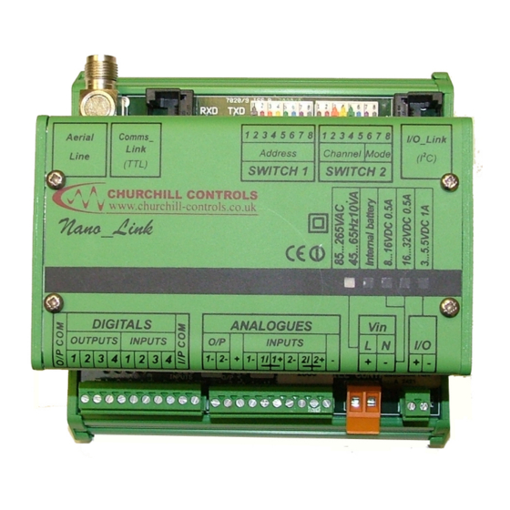
3. Product Description 1 2 3 4 5 6 7 8 1 2 3 4 5 6 7 8 Comms_ Aerial I/O_Link Link Address Channel Mode Line (TTL) SWITCH 1 SWITCH 2 Nano_Link DIGITALS ANALOGUES OUTPUTS INPUTS INPUTS 1- 2- + 1- 1I 1+ 2- 2I 2+ - 1 2 3 4 1 2 3 4 3.1 General Nano_Link is housed in a compact plastic enclosure, which includes an internal power supply and radio or modem, and... -
Page 9: Indicators
3.2 Indicators All Nano_Link’s include four LED’s, designated RXD, TXD, Test and Heartbeat. TXD and RXD monitor communications between the main processor and the radio or modem. It should be noted that the radio acknowledges each character sent to it, so whenever the TXD LED flashes on a Nano_Link equipped with a radio, the RXD flashes in sympathy. -
Page 10: Universal Mains Power Supply
3.3.2 Universal Mains Power Supply An internal mains power pack can be fitted, which derives a 5.3V supply from any input in the range 80…260VAC. The supply includes rechargeable Ni-Cad batteries, which will support the unit in the event of a mains power failure. Nano_Link monitors the battery voltage as an analogue value that can be read by the base-station, and generates a digital alarm if it drops below a defined level. -
Page 11: External 5V Source
Connections to the 7041 controller are via screw terminals, as follows: 1 Solar Panel –ve Solar Panel +ve 3 Battery –ve Battery +ve 5 Battery Low Alarm Battery monitor 7 Output –ve Output +ve Terminals 7 and 8 should be connected to Vin – and + respectively on Nano_Link. Terminal 5 can be connected to any of the digital inputs on Nano_Link if required. -
Page 12: Pseudo Digital Input 1 - Comms Fail Alarm
V+ is equal to the raw input voltage (i.e. 3.0...5.5V) when Nano_Link is asleep, and 5.0V when it is awake. Nano_Link records the current state of each digital input. In addition, it maintains an internal 16-bit counter for each input, which is incremented each time the contact closes. Each input can therefore be used to monitor a digital state or to count input pulses. -
Page 13: Analogue Inputs
3.4.3 Analogue Inputs Nano_Link has two real inputs and two pseudo inputs (which read the battery voltage and the radio received signal strength): 3.4.3.1 Real Inputs: The two real inputs are very similar, and are read to a resolution of 12-bits (i.e. 0…4095). The equivalent circuit of input 1 is as follows: 10Vsw 47H... - Page 14 A N A L O G U E S A N A L O G U E S O / P I N P U T S O / P I N P U T S External supply +10…24V 3-wire current transducer with common 0V, 3-wire current transducer with common 0V, powered by Nano_Link externally powered...
-
Page 15: Potentiometer Interface
3.4.3.1.1 Potentiometer Interface Some transducers incorporate a potentiometer that needs to be energised by a stable voltage, and returns a voltage that varies from 0 to 100% of the energising voltage. A small interface module, designate 7023-1 is available to power a potentiometer from a stable supply derived from the analogue + &... -
Page 16: Pseudo Analogue Input 1 - Supply Volts
3.4.3.2 Pseudo Analogue Input 1 - Supply Volts Nano_Link measures the internal battery voltage, and stores it as if it was an additional analogue input. This register be accessed in two ways: 1. Using the Alphanumeric Display Module (described in section 10). This scales the register contents and displays the actual voltage. -
Page 17: Analogue Outputs
This can be illustrated graphically as follows: 1000 2000 3000 4000 Value The calculated value can be read via Micro_Link. If using method 3 above. However, if using method 1 or 2 the value will be scaled appropriately. The radio receiver has a sensitivity of about -10dBV, and a good radio path should have a margin of at least 10dBµV so the RSSI should ideally read at least 0dBµV, or 1500. -
Page 18: 7150-1 Digital Input Module
3.4.5.1.1 7150-1 Digital Input Module - + - + - + - + - + - + - + - + I/O_Link I/O_Link INPUTS INPUTS Digital Input Module SWITCH 1 INPUTS INPUTS 10 11 12 13 14 15 16 Address Mode + - + - + - + - + - + - + - + - 1 2 3 4 5 6 7 8... -
Page 19: 7150-2 Digital Output Module
3.4.5.1.2 7150-2 Digital Output Module B A B A B A B A B A B A B A B A I/O_Link I/O_Link OUTPUTS OUTPUTS Digital Output Module SWITCH 1 OUTPUTS OUTPUTS 10 11 12 13 14 15 16 Address Mode 1 2 3 4 5 6 7 8 A B A B A B A B A B A B A B A B... -
Page 20: Installation
4. Installation 4.1 Mechanical Data_Link 2000 outstations and base-stations are usually supplied in either steel or polycarbonate enclosures that can be attached to a wall using conventional fixings. The smaller polycarbonate enclosures provide a high degree of protection against water ingress, and care is needed to ensure this isn’t compromised by the method of installation. Most enclosures include cable glands, which are supplied with blanking plugs to maintain a seal. -
Page 21: Surge Protection
4.3 Surge Protection Any external cables are susceptible to surges induced from lightning and electrical power distribution faults. Cables at exposed sites on high ground (such as water reservoirs) is particularly susceptible. Lightning is caused by a build up of static charge in the atmosphere which ultimately causes a flashover. A lightning strike dissipates enormous amounts of energy. -
Page 22: Configuration
5. Configuration Switches S1 and S2 are used to set all configurable parameters in Nano_Link. The software checks the switches every second. If there are any changes the processor will be reset to action the new state. All switches are defined as logic 0 when open or off, and logic 1 when closed or on. -
Page 23: S2.1
01001 458.7250 11001 458.7375 00101 458.7500 10101 458.7625 01101 458.7750 11101 458.7875 00011 458.8000 10011 458.8125 01011 458.8500 11011 458.8625 00111 458.8750 10111 458.8875 01111 458.9125 11111 458.9250 These switches are only relevant if Nano_Link is equipped with an internal UHF radio. Note that the channels are at 12.5KHz spacing, but omit frequencies of 458.8250MHz, 458.8375MHz and 458.9000MHz, in accordance with MPT1329. -
Page 24: Specifications
6. Specifications a) 3 x Alkaline D cells giving 2 years operation* POWER SUPPLY: b) 230/240V AC @ 10VA, max. with 8 battery back-up c) 110/120V AC @ 10VA, with battery back-up d) External 10…15V DC @ 1A max. d) External 3.0...5.5V DC @ 1A max. * Battery life based on power-save mode with 100ms transducer settling time, interrogated every 15 minutes HARDWARE I/O:... -
Page 25: Nano_Link As An Outstation
7. Nano_Link as an Outstation When configured as an outstation (S1 not set to 00000000), Nano_Link can be interrogated by either a Micro_Link or a Nano_Link base-station. It can operate continuously or in a power-saving mode. In continuous mode the power consumption is too high for operation from internal batteries for extended periods, so it is assumed to be mains- powered (although it could be operated from a solar panel or from external batteries). -
Page 26: Sleep Mode
distant outstations. Each time a command is received the outstation re-starts the Stay Awake period. When the Stay Awake period lapses, the outstation will switch to Sleep Mode: 7.1.2.4 Sleep Mode The outstation switches off all internal functions, except for a very low power timer, so power consumption is minimised. -
Page 27: Power-Save Mode, Analogue Averaging (S2.6
sends data to continuously-powered outstations. However, if the outstation reports that it uses digital outputs, a Nano_Link base-station will automatically send data to it as well as reading from it. Obviously, the power consumption in this mode is higher than in normal power-saving mode. 7.1.7 Power-save mode, analogue averaging (S2.6…S2.8 = 011) This mode is similar to the other power saving modes described above, but makes provision for ‘noise’... -
Page 28: Outstation Alarm Handling
7.2 Outstation Alarm Handling As well as indicating fault conditions on the Heartbeat LED (as described in section 3.2), a Nano_Link outstation also indicates them on digital outputs (if equipped). It does this by logically ANDing the digital inputs sent to it by the remote station with the alarm flags. -
Page 29: Nano_Link As A Base-Station
8. Nano_Link as a Base-station Nano_Link configured as a base-station (S1 = 00000000) can only interrogate one outstation. The default base-station address is 0, which will interrogate outstation address 1. However, in areas of dense usage there could be more than one Nano_Link system operating on the same radio channel. -
Page 30: Radio Path Test Set (S2.6
The relevant RSSI levels can be deduced from the output currents using the following graph: 10.0 15.0 20.0 The radio receiver has a sensitivity of about -10dBV, and a good radio path should have a margin of at least 10dBµV so the RSSI should ideally read at least 0dBµV, or 7.5mA, in each direction. -
Page 31: Base-Station Alarm Handling
8.2 Base-station Alarm Handling As well as indicating fault conditions on the Heartbeat LED (as described in section 3.2), a Nano_Link base-station also indicates them on digital outputs (if equipped). It does this by logically ANDing the digital inputs sent to it by the remote base-station with the alarm flags. -
Page 32: Special Features Of Nano_Link
9. Special Features of Nano_Link As described in Section 0, Nano_Link can be configured in a number of special modes that set it to particular functions. All configuration is carried out via the switches S1 and S2, with the exception of shaft encoders, which rely on the use of an Alphanumeric Display Module, as described below. -
Page 33: Hardware Configuration
The encoder power consumption imposes additional drain on battery-powered outstations, so it is optimised by pulsing power when the shaft is stationary. If movement is detected power is maintained until the shaft again becomes stationary. By this means the average power consumption of the shaft encoder is reduced to approximately that of Nano_Link itself. -
Page 34: Exception Reporting
9.3 Exception Reporting Nano_Link outstations fitted with software version V2.0 or later support exception reporting. This feature is configured via commands sent to the outstation from a Micro_Link base-station, not by configuration of the outstation. The method of implementing exception reporting at the base-station is described in the Data_Link 2000 Technical Manual. -
Page 35: Test Modes
9.4 Test Modes Selecting an address on switch S1 above 251 puts the module into a test mode. In the following the switch positions are given in the sequence 12345678, with logic ‘1’ representing a switch closed: 9.4.1 Address 255 (S1 = 11111111) - Power down In this mode all functions of Nano_Link are switched off, except for a low power timer. -
Page 36: Address 252 (S1 = 00111111) - Calibrate Analogues / Test Hardware Outputs / Reset Counters
9.4.4 Address 252 (S1 = 00111111) – Calibrate Analogues / Test Hardware Outputs / Reset Counters Setting this address will carry out an action defined by the state of switch S2. Note that calibration of analogues requires an accurate current source and an accurate ammeter, and must follow the procedure listed below. 12345678 Reset Counters: 01010101... -
Page 37: Alphanumeric Display Module
10. Alphanumeric Display Module 10.1 General The Alphanumeric Display Module Mk2 comprises a 4 line by 20 character LCD display, with an I/O_Link interface, plus 3 pushbuttons. The pushbuttons are marked ▲,▼ and ►. It is housed in an ABS enclosure, which can be hand- held, fitted behind a control panel, or clipped to a DIN rail. -
Page 38: Zero Shaft Encoders
No shaft encoder Enabled. OK? Pressing the ▲ and▼ buttons will allow the user to sequence through 1 shaft encoder Enabled. OK? 2 shaft encoders Enabled. OK? Pressing the ► button will accept the number of shaft encoders displayed and return to, for example: 1 shaft encoder Enabled. - Page 39 Radio channel:31 The ▲ and▼ buttons allow the user to sequence through channels 0…31. Pressing the ► button will accept the currently-displayed value. This channel will remain until either: A new value is selected through the display OR Any pole of switch S1 or S2 is changed OR ...
- Page 40 Page 38...
- Page 41 INDEX Aerials ....................................18 Alarm Handling Base-station ..................................29 Outstation ..................................26 Alphanumeric Display Module ............................35 Analogue Inputs ................................11 Potentiometer Interface ..............................13 Pseudo Analogue Input 1 - Supply Volts ........................14 Pseudo Analogue Input 2 - Radio Received Signal Strength Indicator ................14 Real Inputs ...................................11 Voltage Output Transducers............................13 Analogue Outputs................................15 Battery Low alarm................................10...
- Page 42 Sleep Mode................................24 Sniff mode................................23 Transmit Mode ..............................23 Plant I/O .....................................9 Point-to-point link ................................6 Polycarbonate Enclosures..............................4 Power down..................................33 Power Supply ..................................7 External 12/24VDC Source............................8 External 5V Source ................................9 Internal Batteries ................................7 Solar Supply ...................................8 Universal Mains Power Supply ............................8 Power-save mode using digital outputs..........................24 Power-save mode with 30 second transducer settling time ....................24 Power-save mode with 4 second transducer settling time ....................24 Power-save mode, analogue averaging ..........................25...
Need help?
Do you have a question about the Nano Link Series and is the answer not in the manual?
Questions and answers