Advertisement
Table of Contents
- 1 Fitting Guidelines
- 2 Specifications
- 3 Installation Safety Guidelines
- 4 Installation - Mechanical Components
- 5 Installation - Electrical/Electronic Components
- 6 Operation - Safety Guidelines
- 7 Operation - Motor Units
- 8 Operation - Remote Control Handset
- 9 Operation - Electronic Control Unit
- 10 Operation - Getting Started
- 11 Operation - Hitching and Unhitching
- 12 Maintenance
- 13 Troubleshooting
- 14 Product Registration
- 15 Contact Information
- Download this manual
Advertisement
Table of Contents

Subscribe to Our Youtube Channel
Related Manuals for Quattro Titanium EGO400

Summary of Contents for Quattro Titanium EGO400
- Page 1 Model No. EGO400 - Titanium Model No. EM4446 - Enduro REMOTE CARAVAN MOVER Ref: QUATTRO500/600-UM Installation guide and user information. REF: UM 1.0...
- Page 2 Bitte besuchen Sie www.purpleline.co.uk/caravan-movers VOR Installation auf Aktual- isierungen zu Produktspezifikationen, Nutzung, Sicherheit und Einbauvorschriften zu überprüfen. Kunt u terecht op www.purpleline.co.uk/caravan-movers vóór de installatie te controleren of er updates over productspecificaties, het gebruik, de veiligheid of de installatie-instruc- ties. Please visit www.purpleline.co.uk/caravan-movers BEFORE installation to check for any updates on product specifications, usage, safety or installation instructions.
- Page 3 Fig.A Motor B Motor A...
- Page 4 Fig.1 EM4446 EGO400 Fig.2 Fig.3 EGO400 Fig.5 Fig.4 EM4446 Fig.6...
- Page 5 Fig.8 Fig.7 EM4446 EM4446 20mm Disengaged Position Fig.10 EM4446 Engaged Position Fig.11 Fig.12 20mm EGO400 EGO400 Disengaged Position Fig.13 EGO400 Engaged Position...
- Page 6 Fig.16 Fig.14 EGO400/ EM4446 10mm Fig.15 Fig.19 Fig.17 Caravan Floor L – Profile U – Profile Fig.18 185mm (min) 2.8mm to 3.5mm 165mm 30mm to 45mm (min) 85mm (min) 1800mm to 2500mm (max)
- Page 7 Fig.20 Vorderseite des Wohnwagens Voorkant caravan Caravan Front Direzione di marcia Avant de la caravane Frontal de la caravana Fig.21 Motor Motor Draufsicht Bovenaanzicht Overhead View Vista dall’alto Vue aérienne Vista superior Motor Motor...
- Page 8 Fig.22...
- Page 9 Before First Use - Single Axle and Twin Axle Modes Before First Use - Pairing the Handset and Control Unit(s) Page 8 Page 9 Using Your Caravan Mover with Quattro® Technology Page 9 Operation - Getting Started Operation - Hitching and Unhitching...
-
Page 10: Fitting Guidelines
Introduction Thank you for choosing this caravan mover. This product has been produced according to very high standards and has undergone careful quality control procedures. Simply by using the remote control you can move your caravan effortlessly into any position required within operating guidelines. -
Page 11: Installation - Mechanical Components
Before starting installation under the caravan: DO check that the caravan is disconnected from the battery supply and the mains electrical supply. DO only use adapters and accessories that are supplied or recommended by the manufacturer. DO check that the tyres are not over worn (fitting to new or nearly new tyres is the best option). DO make sure that the tyre-pressures are correct to the manufacturer’s recommendation. -
Page 12: Installation - Electrical/Electronic Components
Make sure that the Main Cross Bar (3) and the Cross Actuation Centre Bar (4) are positioned in the middle of the caravan/mover (the centre of the bar is marked). With the main assembly loosely fitted onto the chassis, slide the whole assembly along the chassis until the rollers (Fig.2A or Fig.4A) are 20mm away from the surface of the centre of each tyre (Fig.8 or Fig.12). Two 20mm spacers (30) are provided. It is vitally important that each roller is at exactly the same distance away from the tyre. The whole assembly must be parallel to the caravan/trailer axle. Ideally, align the roller(s) with the centre of each tyre, if clearances permit. When positioning, always ensure there is at least 10mm of clearance between the gearbox and the tyre (Fig.14). Fully tighten the four nylock nuts (17) on both clamping assemblies (Fig.16) to a torque setting of 40 ft lbs/55Nm, then the four bolts (Fig.1B) on the Main Cross Bar (3) and the four bolts (Fig.1C) on Cross Actuation assembly (4 & 5) to a torque setting of 9ft lbs/12Nm. Re-check the distance of 20mm from the rollers to the tyres and if necessary, loosen the bolts and re-adjust the position of the assembly. Once satisfied with the position of the assembly, fit and tighten the Chassis Stop Nuts & Bolts (7) , one pair in each of the Upper Classic Clamp Plates (see Fig.16). Tighten to a torque setting of 40 ft lbs/55Nm. The Stop Bolts grip the lip of the chassis and help prevent the mover from sliding along the chassis. - Page 13 ‘A’ frame. Please refer to table B (below) for fitment of the motor units to the REAR of the axle. Note: If you are fitting two sets of motors onto a twin-axle caravan to form a full Quattro® system then both Table A &...
-
Page 14: Operation - Safety Guidelines
Operation - Safety Guidelines Before use, always check the mover for any damage. When towing or moving the caravan please be aware, at all times, that ground clearance is reduced by 50mm when the Mover has been fitted. To maintain signal strength, always make sure that, during manoeuvring, the distance between the remote control and the caravan does not exceed 5 metres. -
Page 15: Operation - Motor Units
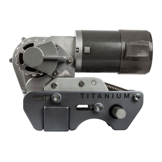
Operation - Motor Units The mover has two Motor Units (1 & 2). In general they are mounted in front of the axle of the caravan/trailer. Both units are identical but cannot be switched. Please refer to Fig.2 for Model No: EGO400 and Fig.4 for Model No: EM4446 Fig.2/Fig4 Drive roller 12V Motor... -
Page 16: Operation - Electronic Control Unit
Before First Use - Single Axle and Twin Axle Modes The following procedure depends on whether you are using the Quattro® electronics for a single axle or twin axle caravan: To enable Single-Axle Mode: Install only 2 of the 3 ‘AAA’ batteries into the battery compartment of the handset (Fig.5). Hold down button Fig.3E and at the same time, install the final battery. -
Page 17: Operation - Getting Started
Also, the amount of different manoeuvres required to locate/park your caravan is increased. However, the advanced electronics of the Quattro® electronics take care of the manoeuvring whilst also taking care of your caravan. -
Page 18: Maintenance
Maintenance To prevent the battery from becoming totally discharged during long periods of inactivity it must be disconnected and recharged before using again. Please check regularly that the rollers of the drive units are free of any dirt, or debris that may have been picked up from the road. - Page 19 Caravan battery could be overloaded. Check electronics box (Blue LED is on and Red LED is flashing continuously). Check your charging equipment and try to discharge the battery by connecting/using a light or other load. If this does not give any result, renew caravan battery before taking any further action.
-
Page 20: Product Registration
Guarantee Quattro® caravan mover systems are provided with a UK parts only warranty for a period of 5-years which includes the first 12 months statutory, plus an additional 4 years extended warranty. Please note that the extended 4 year warranty is only offered if Product Registration is completed and returned within 14 days from the date of purchase. - Page 21 Optional Fitting Adapters Additional chassis clamp adapters are available, as follows: Low Profile Chassis Adapter Plates (Part No. CM-029) If your chassis frame height is less than 140mm these plates must be fitted to lower the assembly to provide the correct height of 185mm. Drilling of your chassis may be required.
- Page 22 DE: Fotos und Diagramme dienen nur der Veranschaulichung. Das tatsächliche Produkt kann leicht abweichen. Alle Gewichte und Maße sind ca -Angaben. Der Hersteller behält sich das Recht vor, Produkspezifikationen ohne vorherige Ankündigung zu ändern.. E & OE. NL: Foto’s en diagrammen dienen slechts ter illustratie. Het eigenlijke product kan enigszins afwijken. Alle gewichten & afmetingen zijn bij benadering. De fabrikant behoudt zich het recht voor productspecificatie zonder voorafgaande kennisgeving te wijzigen.
Need help?
Do you have a question about the Titanium EGO400 and is the answer not in the manual?
Questions and answers