Table of Contents
Advertisement
I n t e l l i g e n t
M o t o r
C o n t r o l s
cerusind.com | 1.800.962.3787
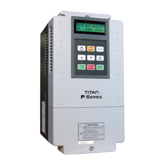
P Series
Fan & Pump Optimized
Variable Frequency Drive
0.5–40HP (200~230VAC) , 3Ø
0.5–700HP (380~480VAC), 3Ø
0.5-150HP (525~600VAC), 3Ø
Dual Rated for Constant & Variable Torque
Integrated PID Control
Application Based Commisioning
Installation, Programming
Operation, & Maintenance
Manual
CAUTION, SAFETY WARNING
As with all electrical products, read manual thoroughly
before operating. Only qualified, expert personnel should
perform maintenance and installation. Contact the nearest
authorized service facility for examination, repair, or
adjustment. Do not disassemble or repair unit; death or
injury due to electrical shock or fire hazard may result.
Product improvement is a continual process at Cerus
Industrial. Specifications and manual data subject to
change.
Consult
factory
for
additional
cerusind.com | 1.800.962.3787
information.
Advertisement
Table of Contents
Troubleshooting

Summary of Contents for CERUS Titan P Series
- Page 1 Do not disassemble or repair unit; death or injury due to electrical shock or fire hazard may result. Product improvement is a continual process at Cerus Industrial. Specifications and manual data subject to change.
- Page 2 Thank you for purchasing CERUS VFD (Variable Frequency Drive)! SAFETY INSTRUCTIONS To prevent injury and property damage, follow these instructions during the installation and operation of VFD. Incorrect operation due to ignoring these instructions may cause harm or damage. The following symbols are used throughout the manual to highlight important information.
- Page 3 WARNING Do not remove VFD cover for wiring or periodic inspections while power is applied or the unit is in operation. Otherwise, electric shock could occur to the exposed terminals and bus bars. Wiring and periodic inspections should be performed at least 10 minutes after disconnecting the input power with DC link voltage below 30VDC.
- Page 4 • Reversing the polarity (+/-) of the digital control terminals can damage VFD. • Only authorized personnel familiar with CERUS VFDs should perform wiring and start- • Perform wiring after VFD installation is done. Otherwise, electric shock or bodily injury •...
- Page 5 (4) Operation When the Auto restart function is selected, VFD can restart multiple times automatically • during operation. The Stop key on the keypad can only be used to stop VFD when Local control is • enabled. Install a separate emergency stop circuit if necessary. •...
-
Page 6: Table Of Contents
Table of Contents CHAPTER 1 - BASIC INFORMATION ....................1-1 1.1 P .................1-1 UMBER ODE AND NITIAL NSPECTION 1.2 B ........................1-2 ASIC CONFIGURATION CHAPTER 2 - SPECIFICATION ......................2-1 2.1 200~230V C 7.5~40HP (5.5~30 W) .....................2-1 LASS 2.2 380~480V C 7.5~40HP (5.5~30 W) .....................2-2 LASS 2.3 525~600V C... - Page 7 CHAPTER 7 - PID CONTROL WIRING AND BLOCK DIAGRAM ..........7-1 7.1 VFD W PID C ......................7-1 IRING FOR ONTROL 7.2 PID C ......................7-1 ONTROL LOCK IAGRAM 7.3 PID ......7-2 CONTROL LEEP MODE WITH LEEP RESSURE OOST FUNCTION DIAGRAM 7.4 PID .
-
Page 8: Chapter 1 - Basic Information
Remove VFD from its packing and inspect its exterior for shipping damage. If there is damage, notify the shipping agent and your CERUS sales representative. Remove the VFD cover and inspect VFD for any damage or foreign objects. Check VFD part number, HP rating and nominal voltage on the sticker attached to the side of the VFD. -
Page 9: Basic Configuration
Chapter 1 – Basic information 1.2 Basic configuration The following devices are required to operate VFD. Proper peripheral devices must be selected and correct connections made to ensure proper operation. An incorrectly applied or installed VFD can result in system malfunction or reduction in product life as well as component damage. -
Page 10: Chapter 2 - Specification
The below tables contain VFD ratings for three-phase and phase-conversion variable torque applications. In order for Cerus to maintain warranty on VFD for phase conversion applications, the customer should call Cerus with application information and line reactor installation is required. -
Page 11: Class 7.5~40Hp (5.5~30Kw)
Chapter 2 - Specification 2.2 380~480V Class 7.5~40HP (5.5~30kW) Part Number (CI-xxx-P4) & UL Type (U1-Type 1, UO-Open Type) Standard Duty Variable Torque 18.5 Motor Rating FLA[A] Heavy Duty Variable Torque or Standard Duty Constant Torque 18.5 Motor Rating FLA[A] Capacity [kVA] 12.7 19.1... -
Page 12: Class 50~125Hp (37~90Kw)
Chapter 2 – Specification 2.4 380 ~ 480V Class 50~125HP (37~90kW) Part Number (CI-xxx-P4) & UL Type (U1-Type 1, UO-Open Type) Standard Duty Variable Torque Motor Rating FLA[A] Heavy Duty Variable Torque or Standard Duty Constant Torque Motor Rating FLA[A] Capacity [kVA] 59.8 72.5... -
Page 13: Class 150~700Hp (110~525Kw)
Chapter 2 - Specification 2.6 380 ~ 480V Class 150~700HP (110~525kW) Part Number (CI-xxx-P4) & UL Type (U1-Type 1, UO-Open Type) Standard Duty Variable Torque Motor Rating FLA[A] Heavy Duty Variable Torque or Standard Duty Constant Torque Motor Rating FLA[A] Capacity [kVA] Output ratings Voltage... - Page 14 Chapter 2 – Specification Emergency Stop Immediately Interrupts the VFD Output in any control method Jog Operation with adjustable Jog frequency Fault Reset Resets VFD. Some critical faults can only be reset by recycling the VFD power. Each relay can be set to Frequency Detection Level, Overload Alarm, Stalling, Four Multi- Over Voltage, Low Voltage, VFD Overheating/ Running/ Stopping/ At Speed, VFD Function Relays...
-
Page 15: Dimensions
Chapter 2 - Specification 2.8 Dimensions 1) CI-007-P2/4 (200/400V Class) and CI-007~015-P6 (600V Class) inches (mm) Model Enclosure Type 5.91 5.12 11.18 10.69 6.16 0.98 0.98 0.98 UL Type 1 CI-007-P2/4 (150) (130) (284) (269) (156.5) (24) (24) (24) IP20 7.87 7.09 13.98... - Page 16 Chapter 2 – Specification 2) CI-010~015-P2/4 (200/400V Class) inches (mm) Model Enclosure Type 7.87 7.09 0.23 11.18 10.69 7.16 1.37 0.98 1.37 UL Type 1 CI-010~015-P2/4 (200) (180) (284) (269) (182) (35) (24) (35) IP20...
- Page 17 Chapter 2 - Specification 3) CI-020~040-P2/4 (UL Open Type with installed UL Type 1 kit) and CI-020~040-P6 (UL Open Type) inches (mm) Enclosure Model Type CI-020-P2/4 9.84 9.06 15.16 14.57 17.88 7.91 5.74 UL Type 1 CI-020-P6 (250) (230) (200.8) (385) (370) (454.2)
- Page 18 Chapter 2 – Specification 4) CI-050~075-P4/6 (UL Open Type 400V and 600V VFDs with installed UL Type 1 kit) inches (mm) Enclosure Model Type 11.81 7.48 0.35 25.28 20.28 10.46 6.43 UL Type 1 CI-050~060-P4 (300) (190) (642) (515) (265.6) (163.4) IP20 CI-075-P4...
- Page 19 Chapter 2 - Specification 5) CI-100, 125-P4/6 (UL Open Type VFD with installed UL Type 1 kit) inches (mm) Enclosure Model Type 14.57 30.22 23.09 13.29 8.66 0.35 UL Type 1 CI-100~125-P4/6 (370) (220) (767.5) (586.5) (337.6) (223.4) IP20 2-10...
- Page 20 Chapter 2 – Specification 6) CI-150~250-P4 & CI-150-P6 (UL Open Type VFDs) inches (mm) Enclosure Model Type CI-150~200-P4 20.08 15.00 0.43 13.78 30.87 29.92 16.64 UL Open CI-150-P6 (510) (381) (11) (350) (784) (760) (422.6) IP00 15.00 0.43 13.78 33.00 UL Open 20.08 33.90...
- Page 21 Chapter 2 - Specification 7) CI-350~ 400-P4 (UL Open Type VFDs) inches (mm) Enclosure Model Type 27.17 22.87 0.55 20.79 42.44 41.14 17.70 UL Open CI-350~400-P4 (690) (580) (14) (528) (1078) (1045) (449.6) IP00 2-12...
- Page 22 Chapter 2 – Specification 8) CI-500~ 700-P4 (UL Open Type VFDs) inches (mm) Enclosure Model Type 30.4 19.7 0.51 19.7 44.9 43.7 17.4 UL Open CI-500-P4 (772) (500) (13) (500) (1141) (1110) (442) IP00 36.3 22.83 0.55 22.83 51.3 50.06 19.5 UL Open CI-600~700-P4...
-
Page 24: Chapter 3 - Installation And Wiring
Chapter 3 – Installation & Wiring CHAPTER 3 - INSTALLATION AND WIRING 3.1 Installation precautions 1) Handle VFD with care to prevent damage to the plastic Temp check components. Do not hold VFD by the front cover. points 2) Do not mount VFD on the equipment with excessive vibration above 5.9 m/sec 3) Install VFD in a location where temperature is within the Temp check... -
Page 25: Basic Wiring Diagrams
Chapter 3 – Installation & Wiring 3.2 Basic Wiring Diagrams 3.2.1 Power wiring diagrams Basic Power wiring for 7.5~600HP (5.5~450kW) VFDs. For single-phase power, connect L1 to R and L2 to S terminals. VFD can malfunction or be damaged if motor and power wires are in the same conduit! Power terminals for 7.5 ~ 40HP (200V/400V/600V) VFDs Jumper R(L1) S(L2) T(L3) - Page 26 Chapter 3 – Installation & Wiring 3.2.2 Basic Control wiring for 7.5~40HP (5.5~30kW) VFDs. Analog inputs wiring with 5G common terminal...
- Page 27 Chapter 3 – Installation & Wiring 3.2.3 Basic Control wiring for 50~700HP (37~525kW) VFDs Note: Use terminal CM for analog inputs, pulse input and ±12VDC power supply common. Analog inputs wiring with CM common terminal...
- Page 28 Chapter 3 – Installation & Wiring 3.2.4 Digital and Analog control circuits terminals layout 7.5~40HP (5.5 ~ 30kW) 200V/400V/600V Class VFDs C+ CM C- M6 24 M7 M8 A0 B0 5G 5G S0 S1 3A 3C 3B A1 C1 A2 C2 A3 C3 A4 C4 M1 CM M2 M3 24 M4 M5 V+ V1 5G V- I NT All CM terminals are connected together and all 5G terminals are connected together internally.
- Page 29 Chapter 3 – Installation & Wiring 3.2.5 Control Inputs and Outputs Description Notes: 1) M1~M8 are Digital Inputs and each can be re-programmed from Normally Open to Normally Closed. 2) Analog Common Terminal: 5G for 7.5~40HP VFDs and CM for 50~700HP VFDs. Type Symbol Name...
- Page 30 Chapter 3 – Installation & Wiring 3.2.6 Power Wiring Wiring Recommendations 1) Do not connect input power to VFD Motor terminals U, V, and W otherwise VFD can be damaged. 2) Do not run input power and motor wires in the same conduit, otherwise the VFD can malfunction or be damaged.
- Page 31 Chapter 3 – Installation & Wiring 3.2.7 Wire sizes and terminal lugs Refer to below table for recommended wires sizes, terminal lugs, and screws for VFD power and motor wiring. Wire size Screw Torque U, V, W (L1) (L2) (L3) VFD capacity HP (kW) kgf ·...
-
Page 32: Control Circuits Wiring
Chapter 3 – Installation & Wiring 3.3 Control Circuits Wiring 3.3.1 Wiring Recommendations The CM and 5G terminals are isolated from each other and from the ground. Do not connect these terminals to the ground, otherwise it can cause some electrical noise in control circuits and unstable VFD operation or malfunction. - Page 33 Chapter 3 – Installation & Wiring 3.3.4 RS485/Modbus RTU communication circuit wiring Use for Modbus-RTU communication terminals C+ for signal High and C- for signal Low. Set the J3 dip switch to ON (Upward) position to connect 120 termination resistor. Connect cable shield to CM or Ground terminals.
-
Page 34: Chapter 4 - Operation
Chapter 4 - Operation CHAPTER 4 - OPERATION 4.1 VFD Programming Keypad 4.1.1 LCD Keypad LCD keypad can display up to 32 alphanumeric characters, and various settings can be checked directly from the display. The following pictures are a dimensional drawing and illustration of the keypad. "... - Page 35 Chapter 5 – Parameter List 4.1.2 Display Description 3) 1 +) , "'▶ 4 5 5 6 * 1 /5 5578 0) 1 " . /) , Displays Description 1) Parameter Group Displays the current parameter group. Parameter groups include: SET, DRV, FG1, FG2, I/O, EXT, COM and APP.
- Page 36 Chapter 5 – Parameter List 4.1.3 Programming the VFD Parameters The navigation through VFD parameters is similar to the book reading process. Finding a desired parameter group is similar to finding a right page in the book- flip pages one after another. Finding a desired parameter in the parameter group is the same as finding a desired line on the book page- scroll Up or Down.
-
Page 37: Control Modes
Chapter 5 – Parameter List 4.1.4 Parameter groups All P Series VFD parameters are divided in eight program groups by functionality. Parameter Group Code Description Set Group Application selection, Motor Data, Basic control and timers settings, PID. Drive Group Step Frequencies and monitoring parameters Max. -
Page 38: Function Settings And Descriptions
Chapter 5 – Parameter List 4.2.4 Local/Remote Control Mode When VFD is controlled remotely and [LOCAL/REMOTE] key is pressed, the VFD control mode changes from remote to local mode based on the parameter SET-90 selection. The parameter DRV-00 should show the following screen with letter L (Local) next to parameter number. - Page 39 Chapter 5 – Parameter List F/B Unit Max. SET-25 Maximum Sensor Rating (Pumps 100PSI and fans 1inWC ) PID SetPoint SET-26 PID control Set-point (50% of the sensor rating) Local RemKey SET-90 Local/Remote Mode Function (Cntl&RefStop) Line Freq. FG1-29 Power Line Frequency (60Hz) Max.
- Page 40 Chapter 5 – Parameter List Last Trip-1~5 FG2-1~5 Last 5 faults with Hz, A, Mode and Time information. LastTripTime FG2-7 Accumulative time counter after last VFD fault relay activation On-Time FG2-8 Accumulative time counter for VFD Powered time Run-Time FG2-9 Accumulative time counter for VFD Run time In Status I/O-28...
-
Page 41: Control Wiring Configurations
Chapter 5 – Parameter List 4.3.8 Saving and Resetting Parameters Parameter Name Code Description (Default Value) Para. Read FG2-91 Reads parameters from VFD and saves to a keypad memory (No) Para. Write FG2-92 Writes parameters from keypad memory to VFD memory (No) Para. - Page 42 Chapter 5 – Parameter List Keypad-1. The frequency in DRV-00 parameter is the 1 Speed and the 2 Speed is activated by M1 input and can be adjusted in parameter DRV-01. 4.4.2 Examples of analog speed control configurations The 4.4.2 picture shows four most common VFD speed control configurations. Config.
- Page 43 Chapter 5 – Parameter List Potentiometer Wiring The picture below shows a VFD speed control potentiometer wiring with VFD internal 12VDC power source. The recommended potentiometer parameters: Resistance from 1k to 10k ; Wattage 0.5W or higher. The multi-turn potentiometer provides more precise speed adjustment compare to a single-turn potentiometer.
-
Page 44: Chapter 5 - Parameter List
Chapter 5 – Parameter List CHAPTER 5 - PARAMETER LIST 5.1 [SET] Setup Parameter Group The parameter codes in gray are hidden until the corresponding feature parameter in bold is activated. The parameters marked with can be changed during run and with in stop mode only. - Page 45 Chapter 5 – Parameter List Com. LCD Keypad CODE Description Setting Range Page Addr Display Adj. 0 (I) SET-21 9115 PID Feedback Signal PID F/B 1 (V1) 2 (Pulse) 0 (PSI) 1 (°F) 2 (°C) 3 (inWC) 4 (inM) SET-22 9116 Feedback Unit Select F/B Unit 5 (Bar) 6 (mBar)
-
Page 46: Set] Parameter Group Default Settings
Chapter 5 – Parameter List Com. LCD Keypad CODE Description Setting Range Page Addr Display Adj. SET-65 9141 Speed VFD ramps down to when Aux starts MMC DecFreq 0 to FG1-30 SET-66 9142 MMC Feedback Start Differential 0.0 to 100.0 [%] AuxStartDiff SET-67 9143 MMC Feedback Stop Differential 0.0 to 100.0 [%]... - Page 47 Chapter 5 – Parameter List Basic LCD Keypad Supply Exhaust Cooling Circul. Subm. Vacuum Const. CODE Display Tower Pump Pump Pump Torq. SET-21 PID F/B SET-22 F/B Unit CUST inWC inWC °F inWC CUST SET-23 Unit Format 0.01 0.01 SET-25 F/B Unit Max 100.0 1.00 1.00...
-
Page 48: Drv] Drive Parameter Group
Chapter 5 – Parameter List 5.3 [DRV] Drive parameter group Comm. LCD Keypad CODE Description Setting Range Page Addr Display Adj. DRV-00 9200 Command/ Output Frequency Cmd. freq DRV-01 9201 Step Frequency 1 Step Freq-1 DRV-02 9202 Step Frequency 2 Step Freq-2 DRV-03 9203... -
Page 49: Drv] Parameter Group Default Settings
Chapter 5 – Parameter List 5.4 [DRV] Parameter Group Default Settings LCD Keypad Basic Supply Exhaust Cooling Circul. Subm. Vacuum Const. CODE Display Tower Pump Pump Pump Torq. DRV-00 Cmd. freq 0.00 [Hz] 0.00 [Hz] 0.00 [Hz] 80.00 [°F] 50.00 [PSI] 50.00 [PSI] 60.00inWC 0.00 [Hz] DRV-01 Step Freq-1 10.00[Hz] 10.00[Hz] 10.00[Hz] 100.0 [°F] 100.0 [PSI] 100.0 [PSI] 100.0inWC 10.00[Hz] DRV-02 Step Freq-2... -
Page 50: Fg1] Function Group 1 Parameter Group
Chapter 5 – Parameter List 5.5 [FG1] Function Group 1 parameter group Com. LCD Keypad Adjust CODE Description Setting Range Page Addr Display 1 to 91 FG1-00 9300 Jump to Desired Code # Jump Code 0 (Linear) 1 (S-curve) FG1-01 9302 Acceleration Pattern Acc. -
Page 51: Fg1] Parameter Group Default Settings
Chapter 5 – Parameter List FG1-58 933A No Motor Trip Current Level NoMotorLevel 5 to 100 [%] FG1-59 933B No Motor Trip Time Setting NoMotorTime 0.1 to 10.0 [Sec] 0 (No) FG1-60 933C Electronic Motor Overload ETH Select 1 (Yes) Electronic Thermal Level for 1 FG1-61 933D... - Page 52 Chapter 5 – Parameter List Basic LCD Keypad Supply Exhaust Cooling Circul. Subm. Vacuum Const. CODE Display Tower Pump Pump Pump Torq. FG1-27 DcBr Value 50 [%] 50 [%] 50 [%] 50 [%] 50 [%] 50 [%] 50 [%] 50 [%] FG1-28 Safety Stop (No) (No)
-
Page 53: Fg2] Function Group 2 Parameter Group
Chapter 5 – Parameter List 5.7 [FG2] Function Group 2 parameter group Com. LCD Keypad CODE Description Setting Range Page Addr Display Adj. 1 to 95 FG2-00 9400 Jump to Desired Code # Jump Code FG2-01 9401 Last trip 1 Last Trip-1 Press [ENTER] then key to see Hz,... - Page 54 0 to 27 0 (Voltage) FG2-81 9451 User Display Selection User Disp 1 (kWatt) 6-21 FG2-82 9452 Software Version CERUS S/W Ver X.XX Display FG2-87 9457 Scaling for Power Meter PowerSet 0.1 to 400.0 % 0 (Default) FG2-90 945A Parameter Display Para.
-
Page 55: Fg2] Parameter Group Default Settings
Chapter 5 – Parameter List 5.8 [FG2] Parameter Group Default Settings LCD Keypad Basic Supply Exhaust Cooling Circul. Subm. Vacuum Const. CODE Display Tower Pump Pump Pump Torq. FG2-00 Jump Code FG2-06 Erase Trips FG2-10 Dwell Time 0 [sec] 0 [sec] 0 [sec] 0 [sec] 0 [sec]... -
Page 56: I/O] Inputs/Outputs Parameter Group
Chapter 5 – Parameter List 5.9 [I/O] Inputs/Outputs parameter group Comm. LCD Keypad CODE Description Setting Range Page Addr Display Adj. 1 to 98 I/O-00 9500 Jump to desired code # Jump Code I/O-01 9501 V1 Input Noise Filtering Time V1 Filter 0 to 9999 [msec] I/O-02... - Page 57 Chapter 5 – Parameter List Comm. LCD Keypad CODE Description Setting Range Page Addr Display Adj. 12 (3-Wire) 13 (Ext Trip) 14 (Pre-Heat) 15 (iTerm Clear) 16 (Open-loop) 17 (LOC/REM) 18 (Analog hold) 19 (XCEL stop) 20 (P Gain2) 21 (- Reserved -) 22 (interlock1) 23 (interlock2) 24 (interlock3)
- Page 58 Chapter 5 – Parameter List Comm. LCD Keypad CODE Description Setting Range Page Addr Display Adj. I/O-55 9537 Deceleration Time 3 Dec Time-3 I/O-56 9538 Acceleration Time 4 Acc Time-4 I/O-57 9539 Deceleration Time 4 Dec Time-4 I/O-58 953A Acceleration Time 5 Acc Time-5 I/O-59 953B...
- Page 59 Chapter 5 – Parameter List Comm. LCD Keypad CODE Description Setting Range Page Addr Display Adj. Programmable Digital Auxiliary Same as I/O-76 I/O-77 954D Aux Relay2 Relay2 Define (A2-C2) Programmable Digital Auxiliary Same as I/O-76 I/O-78 954E Aux Relay3 Relay3 Define (A3-C3) Programmable Digital Auxiliary Same as I/O-76 I/O-79...
-
Page 60: I/O] Parameter Group Default Settings
Chapter 5 – Parameter List 5.10 [I/O] Parameter Group Default Settings Basic LCD Keypad Supply Exhaust Cooling Circul. Subm. Vacuum Const. CODE Display Tower Pump Pump Pump Torq. I/O-00 Jump Code I/O-01 V1 Filter 200 [ms] 200 [ms] 200 [ms] 200 [ms] 200 [ms] 200 [ms]... - Page 61 Chapter 5 – Parameter List Basic LCD Keypad Supply Exhaust Cooling Circul. Subm. Vacuum Const. CODE Display Tower Pump Pump Pump Torq. I/O-72 S1 Mode 1 (Current) 1 (Current) 1 (Current) 1 (Current) 1 (Current) 1 (Current) 1 (Current) 1 (Current) I/O-73 S1 Adjust 100 [%]...
-
Page 62: App] Application Parameter Group
Chapter 5 – Parameter List 5.11 [APP] Application parameter group Comm. LCD Keypad CODE Description Setting Range Page Addr Display Adj. APP-00 9600 Jump to Desired Code # Jump Code 1 to 78 APP-01 9601 PID F Gain Selection PID F Gain 0 to 999.9[%] 0 (No) PID Auxiliary Reference Mode... - Page 63 Chapter 5 – Parameter List Comm. LCD Keypad CODE Description Setting Range Page Addr Display Adj. APP-68 9644 Auto Change Level AutoEx Level FG-32 to FG1-30 [Hz] 0 (No) APP-69 9645 Inter-Lock Selection Interlock 1 (Yes) 0 (No) APP-78 964E Ext PID Operation Selection Ext PI Mode 1 (Yes)
-
Page 64: App] Parameter Group Default Settings
Chapter 5 – Parameter List 5.12 [APP] Parameter Group Default Settings Basic LCD Keypad Supply Exhaust Cooling Circul. Subm. Vacuum Const. CODE Display Tower Pump Pump Pump Torq. APP-00 Jump Code APP-01 PID F Gain 0.0 [%] 0.0 [%] 0.0 [%] 0.0 [%] 0.0 [%] 0.0 [%]... -
Page 65: Ext] Extension Parameter Group
Chapter 5 – Parameter List 5.13 [EXT] Extension parameter group Com. LCD Keypad CODE Description Setting Range Page Addr Display Adj. EXT-00 9700 Jump Code Jump Code 1 to 45 EXT-01 9701 Type of SUB Board Sub B, D or E Sub-B to E Display EXT-40 9728... - Page 66 Chapter 5 – Parameter List Com. LCD Keypad CODE Description Setting Range Page Addr Display Adj. 0 20 1 21 COM-12 980C Out Net Instance Out Instance 2 100 3 101 (70) (71) COM-13 980D DeviceNet Input Instance In Instance (110) (111) COM-17 9811...
-
Page 67: Com] Parameter Group Default Settings
Chapter 5 – Parameter List 5.16 [COM] Parameter Group Default Settings LCD Keypad Basic Supply Exhaust Cooling Circul. Subm. Vacuum Const. CODE Display Tower Pump Pump Pump Torq. COM-00 Jump Code COM-02 Opt Mode None None None None None None None None COM-10 MAC ID... -
Page 68: Chapter 6 - Parameter Description
Chapter 6 - Parameter Description The Circulating Pump selection provides CHAPTER 6 - PARAMETER constant pressure PID control with pressure DESCRIPTION transducer feedback. The process unit is set to PSI with 0-100PSI transducer range and 50PSI set-point. 6.1 Setup group [SET] The sleep mode is enabled and parameters are set to optimal values, which should be readjusted for better performance based on the system parameters... - Page 69 Chapter 6 - Parameter Description )* + " # " !- )*3+ $! ' ( " Motor HP VAC 480.0 V VAC 230.1 V The HP rating from the 7.5 HP 109.1 % 104.6 % motor nameplate should be put in this parameter. The input power voltage value is a percentage of The default setting for this rating can be changed by the VFD basic voltage 440V and 220V.
- Page 70 Chapter 6 - Parameter Description parameter DRV-00. Use the [Shift] key to move the adjustable in I/O group parameters. flashing cursor to proper position to make fast or slow change of the speed reference value. When V1 is selected, the VFD speed is "...
- Page 71 Chapter 6 - Parameter Description Max. Hz. It will take 10sec to accelerate from 20Hz frequency is below FG1-25 setting. DC to 30Hz with ACC set to 60sec. and max. speed set injection brake provides a faster stop for the to 60Hz.
- Page 72 Chapter 6 - Parameter Description provide optimal and stable control. ) .+ $ 8 9 ! " ).*+ $ $! -" Unit Format The Unit Format PID I Time parameter has selection The I-Time 1.0 sec for 0.1 or 0.01. In order to provide more accurate determines how much control if transducer range is low or set point of the process error will be accumulated and used...
- Page 73 Chapter 6 - Parameter Description should be set high enough to increase system )/ 6 / 6 /.+ ;" 9 ! " 2' ! 6 pressure above set point. When the system pressure is increased above set point by SET-34 value, the PBroken Freq PBroken Dly VFD will switch to Sleep mode and stop based on...
- Page 74 Chapter 6 - Parameter Description )7 6 0*+ 1 % ?) " " " 2' ! )77+ 1 % ?)/ " " " 2' ! Start Freq 4 59.00 Hz Start Freq 1 Aux Start DT 59.00 Hz 5.0 sec When VFD runs at speed exceeding SET-55 If SET-50 is set to Yes, SET-51 is set to more than with AUX-1, AUX-2 and AUX-3 motors running...
- Page 75 Chapter 6 - Parameter Description If SET-66 and SET-67 are set to 0.0%, VFD )34+ & starts and stops AUX motors only based on LDT Level start/stop Frequencies and Delays and does not The SET-78 LDT Level 9.0 A monitor feedback signal. parameter sets the trigger point for LDT function.
- Page 76 Chapter 6 - Parameter Description )5*+ LocalRemKey The SET-90 parameter Cntl&RefStop has seven selections: 2 Source, Cntl&RefStop, Control Stop, Ref Only, Cntl&RefRun, Control Run, Disabled. • 2 Source- changes control to a second source determined by parameters DRV-91 & DRV-92. •...
-
Page 77: Drive Group [Drv]
Chapter 6 - Parameter Description 6.2 Drive Group [DRV] ) 0+ B - " 2' ! Jog Freq )**+ 1 " 2' ! If any digital input I/O- 10.00 Hz " 2' ! ! 1'"" ! 20~27 is programmed to Jog_FX or Jog_RX and activated, the VFD will 0.0A Cmd. - Page 78 Chapter 6 - Parameter Description transducer range. The [O] Output value is a shown with unit set in SET-22 and it is very useful for PID operation trouble-shooting. percentage of the VFD maximum output frequency. This parameter display is very useful for EXT-PID ) /+ "...
-
Page 79: Function Group 1 [Fg1]
Chapter 6 - Parameter Description − (( $ + FGGHI JKLH = 6.3 Function Group 1 [FG1] The Actual !(( $ % &'(!*) $ !(( $ % &'(!*N $ " " )**+ B' − (" $ + OHGHI JKLH = Jump Code The Actual The FG1-00 parameter... - Page 80 Chapter 6 - Parameter Description + " )# & Output Frequency Speed Reference FG1 PreHeatLevel PreHeat Duty The FG1-11 parameter determines the pre-heat Start current as a percentage of SET-03 Motor FLA. Time Frequency Increase this level from default setting if ambient Output Voltage temperature is lower than 41°F (5°C).
- Page 81 Chapter 6 - Parameter Description DC Braking is activated. acceleration will output 230V at 60Hz and from this FG1-26 is the setting for DC Braking operating point increase only frequency to 70Hz. time. FG1-27 is the setting for DC Braking current as a ).
- Page 82 Chapter 6 - Parameter Description User V/F curve. temperature of the VFD running at full speed with Output Voltage ambient temperature less than 77°F should be less than 60°C. 100% FG1-48 )70+ " " '" E1 FG1-46 Motor Temp. FG1-44 FG1-42 Output Frequency...
- Page 83 Chapter 6 - Parameter Description level for FG1-68 time, the VFD will trip on Motor Overload fault. Current % )05+ $! ' " ETH 1 min Trip Select FG1-69 has a 3-bit selection system ETH cont starting from the right to the left to enable bit #1 Trip Time Output Phase Loss, Bit #2 Input Phase Loss, Bit #3 1 minute...
- Page 84 Chapter 6 - Parameter Description run current, the VFD can create an output speed Accel/Decel time decimal point: 0.01sec., 0.1sec., oscillation. 1sec. The default setting is sufficient for most Fan and 0.01sec- This selection provides more precise Pump applications. Accel/Decel time adjustment but limits it to 60.00sec.
-
Page 85: Function Group 2 [Fg2]
Chapter 6 - Parameter Description 6.4 Function Group 2 [FG2] When FG2-10 is set to 1~6000sec., the dwell function is enabled. The VFD will ramp up to FG2- 11 frequency and stay at that frequency for FG2-10 )**+ B' time and then continue ramping up to the speed Jump Code reference frequency. - Page 86 Chapter 6 - Parameter Description Output Frequency ) /A 0+ " " 6 ' 8 " ! Max. Freq. FG2-16 High3 FG2-15 Low3 Retry Mode Retry Number VFD will skip any frequency reference set FG2-14 High2 between Low and High FG2-13 Low2 frequency settings Retry Delay...
- Page 87 Chapter 6 - Parameter Description for internal calculations for accurate speed control )0*A0.+ 1 ! " 6 %' in Slip Compensation and Sensorless modes. The '! !-6 F default value is set based on standard industrial ControlMode Auto Tuning motor parameters and the capacity of the VFD. If motor name plate does not have No Load rating, it can be determined by running motor without load %Lsigma...
- Page 88 )03A05+ "2' ; !' %' 6 "( " & " )4 + > ( " " CERUS S/W FG2 Torque Boost Fwd Boost Ver. 1.0 Manual 2.0 % FG2-82 shows the VFD firmware version number. Rev Boost If VFD parameters were saved to a keypad with 2.0 %...
- Page 89 Chapter 6 - Parameter Description )5 + " " " >" Para. Write FG2-92 allows loading all previously saved VFD parameters from keypad to VFD memory. When VFD is at stop mode and FG2-92is set to Yes, the VFD parameters will be loaded from Keypad to VFD memory.
-
Page 90: Input/Output Group [I/O]
Chapter 6 - Parameter Description 6.5 Input/Output Group [I/O] I/O-04 should be set to the maximum analog voltage signal value. For example, if voltage signal from BMS is 0-5VDC, I/O-04 should be set to $ )**+ B' 5VDC. The default value is 10VDC and can be Jump Code changed from 0 to 12VDC. - Page 91 Chapter 6 - Parameter Description current signal value. For example, if current signal Pulse voltage high and low levels of Open from BMS is 4-20mA, I/O-09 should be set to Collector Transistor output from Encoder 20mA. The default value is 20mA and can be VFD Terminals Pulse Level changed from 0 to 20mA.
- Page 92 Chapter 6 - Parameter Description any available selection. The table below shows the default settings for all eight inputs. Speed-L, M, H and X- VFD can run at different preset speeds based on digital inputs combinations shown in table for DRV-01~15. Code Default XCEL-L, M and H- If M1, M2 and M3 inputs are...
- Page 93 Chapter 6 - Parameter Description Interlock 1, 2, 3 & 4- This function is used for $ ) 4+ $! ' MMC operation to disable and remove any In Status auxiliary motor from the normal start/stop 00001000000 sequence. When MMC is enabled and M1, M2, M3 or M4 is set to Interlock and activated, the The I/O-28 parameter shows real time inputs status corresponding AUX relay output will be disabled.
- Page 94 Chapter 6 - Parameter Description digital input is set to Damper Switch in I/O-20~27, XCEL Parameter Accel/Decel the VFD will start the motor only when tDamper Code Time # Switch closes. If it is not activated during I/O-69 (M3) (M2) (M1) Damper Timer, the VFD will trip on Damper Fault.
- Page 95 Chapter 6 - Parameter Description For example: if I/O-71 is set to 50%, the maximum Setting Range Description analog output will be 5VDC at maximum output frequency. INV line VFD- Bypass outputs COMM line [Current] SSearch Speed search mode is ON S0 or S1 output provides 0-10VDC signal Ready VFD is ready...
- Page 96 Chapter 6 - Parameter Description Output Frequency Output Current FG1-64 [OL level] I/O-74 I/O-75 I/O-75/2 Time Time Relay Relay Time [FDT-4] The selected AUX relay will be closed when the [IOL] output frequency reaches I/O-74 FDT frequency. The selected AUX relay will be closed when the The AUX relay will then open when output output current is above 110% of VFD current rating frequency falls below [I/O-74]-([I/O-75]/2).
- Page 97 Chapter 6 - Parameter Description inputs. DC Link Voltage Output Frequency OV Level Speed Search Time Time Command Relay Exchange Input Time Bypass [LV] Contactor The selected AUX relay will be closed when the DC link voltage is below the Low-voltage level Contactor (200VDC for 240V line voltage setting and 400VDC for 480V line voltage setting).
- Page 98 Chapter 6 - Parameter Description an Under level condition for the source in SET-75. $ )4/6 47+ 1 " '" If Parameter Set-74 is set to Over Level detection. Fan Control Fan Temp The selected AUX relay closes when VFD detects Power On an Over level condition for the source in SET-75.
- Page 99 Chapter 6 - Parameter Description The VFD display will show LOR fault at com. loss. I/O-94 setting is for communication using RS232- RS485 converter and should be set according to converter specification. This time setting creates a delay before VFD sends response. $ )57+ "...
-
Page 100: Application Group [App]
Chapter 6 - Parameter Description 6.6 Application Group [APP] )*5+ $ " & & ! < PID D Time )**+ B' The Derivative 0.0 sec parameter of the PID Jump Code APP-00 allows jumping control allows creating an offset on the PID output to any parameter in value based on rate of error change. - Page 101 Chapter 6 - Parameter Description ) 6 .+ >" 2' ! )/ + > " 1 %': " "! % "! APP 2nd BaseFreq 2nd V/F APP Starting Aux APP-41 shows the 60.00 Hz Linear actual run time for Aux APP-22- The second acceleration time setting.
- Page 102 Chapter 6 - Parameter Description Main- the alternation mode is enabled and VFD )4*+ : "! will alternate auxiliary motors on the VFD output ExtSetPoint by run time timer. APP-80 determines the 50.0 % Line Power VFD Output to Motors external PID set-point value as a percentage of the maximum feedback External...
- Page 103 Chapter 6 - Parameter Description )5*+ : "! APP ExtPID Scale APP-90 sets the 100.0 % external PID output scaling factor. The default is 100% and it is optimal for most of the applications. )5 + : "! APP Ext P2 Gain APP-91 sets the 100.0 % external PID second P-...
-
Page 104: Extension Group [Ext]
Chapter 6 - Parameter Description 6.7 Extension Group [EXT] [Ext.PID Out] CO1 or CO2 output provides 4-20mA signal corresponding to VFD External PID output from 0 ? )**+ B' to 100%. Jump Code EXT-00 allows jumping to any parameter in EXT group without scrolling to it. Press [ENTER] key and put a desired parameter code by using [SHIFT] and [UP]/[DOWN] keys. -
Page 105: Communication Group [Com]
Chapter 6 - Parameter Description 6.8 Communication Group [COM] ) *+ %1 $ MAC ID The communication option card manual provides a COM-10 allows to set detailed description of the installation, wiring and MAC ID from 0 to 63. set-up procedures. ) + ;... - Page 106 Chapter 6 - Parameter Description )/*+ $! ' ' 8 " Input Num COM-40 allows to set input number from 0 to )/ A/4+ $! ' % " <# ?= Input1 COM-41 through 0005 COM-48 are parameters for eight communication input address settings.
-
Page 108: Chapter 7 - Pid Control Wiring And Block Diagram
Chapter 7 – PID Control CHAPTER 7 - PID CONTROL WIRING AND BLOCK DIAGRAM 7.1 VFD Wiring for PID Control The keypad is normally used R(L1) for PID set-point adjustment. Power Any digital input can be S(L2) MOTOR Input programmed for Open-Loop function, which allows to T(L3) disable PID and control VFD... -
Page 109: Pid Control Sleep Mode With Sleep Pressure Boost Function Diagram
Chapter 6 - Parameter Description 7.3 PID control Sleep mode with Sleep Pressure Boost function diagram. -
Page 110: Pid Control With Pipe Broken Function Diagram
Chapter 6 - Parameter Description 7.4 PID control with Pipe Broken function diagram. -
Page 111: Pid Control With Pre-Pid Function Diagram
Chapter 6 - Parameter Description 7.5 PID control with Pre-PID function diagram. -
Page 112: Pid Control Setting Notes
Chapter 6 - Parameter Description 7.6 PID Control Setting Notes:... -
Page 114: Chapter 8 - Troubleshooting & Maintenance
Chapter 8 - Troubleshooting & Maintenance CHAPTER 8 - TROUBLESHOOTING & MAINTENANCE 8.1 Fault Display When VFD trips on any fault, VFD turns off its output and displays the fault status in DRV-21. The last five faults are saved in FG2-01~05 with the operation parameters and status at the trip moment. Protective Keypad Display Description... -
Page 115: Fault Remedy
Chapter 8 - Troubleshooting & Maintenance 8.2 Fault Remedy Protective Cause Remedy Function Over Current 2 Short circuit between the upper and lower IGBTs. Check IGBT with multimeter in diode check mode. Short has occurred in motor circuit or windings. Check motor wiring and windings. -
Page 116: Troubleshooting
VFD output terminals. Check VFD output voltage corresponding to the output frequency. If VFD is running at some frequency and there is no output voltage, call Cerus tech support. The motor rotates in If VFD is running and shows FWD but motor rotates in reverse direction, stop opposite direction. - Page 117 Chapter 8 - Troubleshooting & Maintenance Check diodes in the rectifier bridge and IGBT module with multimeter in the sequence shown in below table and diagram. Diode state codes: C- Closed and O- Open. M/C Contact Six- Pulse Rectifier Bridge DC Bus Positive IGBT transistors (P1+)
-
Page 118: Maintenance
If debris build up cannot be removed easily, call Cerus for support. ☞ Check for any discoloration or visual damage to the various connectors inside the VFD. Call Cerus for support if any discolored or damaged connectors are found. - Page 119 Chapter 8 - Troubleshooting & Maintenance 8.5.4 Maintenance and Inspection Scheduling Measuring Every Inspection Method Criteria Instrument Inspection Equipment Is there any abnormal vibration or No special tools required No abnormality Ο noise? Input Is the input voltage of the main circuit Measure the voltage between the Stable line Digital...
-
Page 120: Chapter 9 - Options
Chapter 9 - Options CHAPTER 9 - OPTIONS 9.1 Option List Keypad 32 character display All units keypad Download and Upload available Remote Remote cable 6, 9 and 15-foot long keypad cable to Optional control VFD from remote keypad. Dynamic DB unit and Allows VFD to decelerate rapidly without Optional... -
Page 121: The Basic Wring Diagram For Dynamic Braking Unit And Resistor
Chapter 9 - Options 9.5 The basic wring diagram for Dynamic Braking Unit and Resistor. Notes: 1. Use 600V rated twisted wires for DBU and DBR wiring. 2. If DBU overheat protection terminals are labeled CM and OH, this is an open collector transistor output rated 100mA up to 30VDC and it will be closed when DBU trips on overheat. -
Page 122: Dbu Frame 1 Dimensions
Chapter 9 - Options 9.6 DBU Frame 1 dimensions LED indication description table Description When DB unit heat sink temperature exceeds the internal setting, the Unit trips on Overheat and (GREEN) OHT LED will be ON. POWER POWER LED is ON while VFD is powered. (RED) RUN LED flashes when DBU sends regenerated energy to resistor. -
Page 123: Dbu Frame 2 Dimensions
Chapter 9 - Options 9.7 DBU Frame 2 dimensions mm (inches) Description RESET Press this button to reset OCT FAULT. POWER When DB unit heat sink temperature exceeds the internal setting, the Unit trips on Overheat and (GREEN) OHT LED will be ON. POWER LED is ON while VFD is powered. -
Page 124: Dbu Frame 3 Dimensions
Chapter 9 - Options 9.8 DBU Frame 3 dimensions mm (inches) Description POWER When DB unit heat sink temperature exceeds the internal setting, the Unit trips on Overheat and (GREEN) OHT LED will be ON. POWER LED is ON while VFD is powered. (GREEN) OHT (RED) RUN LED flashes when DBU sends regenerated energy to resistor. -
Page 125: Dynamic Braking Resistor Sizing
Chapter 9 - Options 9.9 Dynamic Braking Resistor Sizing When dynamic braking is required for the application, the dynamic braking resistor should be sized based on the table below. Determine an ED (Enable Duty) cycle and continuous braking time and select proper resistor values. - Page 126 Chapter 9 - Options [Conduit box for 030~040HP VFD] [Conduit box for 050~075HP VFD] [Conduit box for 100~125HP VFD]...
- Page 127 Chapter 9 - Options Conduit Hole Size mm(inches) Conduit hole for control terminal Size of the Conduit Conduit hole for power terminal 24 (0.98) 16 (1/2) CI-007-P2/4 24 (0.98) 16 (1/2) 24 (0.98) 16 (1/2) CI-010-P2/4 35 (1.37) 27 (1) 24 (0.98) 16 (1/2) CI-015-P2/4...
-
Page 128: Chapter 10 - Modbus-Rtu Communication
Chapter 11 – Modbus-RTU Communication CHAPTER 10 - MODBUS-RTU COMMUNICATION 10.1 Introduction VFD can be controlled and monitored via communication by the BMS, PLC or other master module. Drives or other slave devices may be connected in a multi-drop Modbus-RTU network with up to 31 units and may be monitored or controlled by a single master control device. -
Page 129: Communication Parameters
Chapter 10 – Modbus-RTU Communication 10.3 Communication Parameters Parameter Display Name Set value Unit SET-09 Drive mode Drive mode Int. 485 SET-10 Freq mode Freq mode Int. 485 I/O_20~27 M1 ~ M8 Programmable Digital Inputs I/O_90 Inv Number VFD ID number 1~250 I/O_91 Baud rate... -
Page 130: Parameter Code List
Chapter 10 – Modbus-RTU Communication 10.5 Parameter code list <Common area>: Area accessible regardless of VFD models Address Parameter Unit Unit R/W Data value 0x0000 VFD model R 9 : P series 4: 5.5kW, 5: 7.5kW 6: 11kW, 7: 15kW, 8: 18.5kW VFD capacity 9: 22kW,... - Page 131 Chapter 10 – Modbus-RTU Communication Address Parameter Unit Unit R/W Data value BIT13: REM. R/S (Int. 485, OPT) BIT14: REM. Freq. (Int. 485, OPT) BIT 0 : OCT1 BIT 1 : OV BIT 2 : EXT-A BIT 3 : BX BIT 4 : LV BIT 5 : RESERVE BIT 6 : GF(Ground Fault)
- Page 132 Chapter 10 – Modbus-RTU Communication Detailed description of the address 0x0006 Value Name Description 0x01 Stop Stop command via communication (0 1) 0x02 Forward run Forward run command via communication (0 1) 0x04 Reverse run Reverse run command via communication (0 1) 0x08 Fault reset Fault reset command via communication (0 1)
-
Page 133: Chapter 11 - Appendix "A"- Ul Marking
Chapter 11 – Appendix-A UL Marking CHAPTER 11 - A “A”- UL M PPENDIX ARKING 11.1 Short Circuit Interrupting Rating “Suitable for use on a circuit capable of delivering not more than Table1 RMS Symmetrical Amperes, 240V for 240V, 480V for 480V, 600V for 600V rated VFDs Volts Maximum,” Table 1. -
Page 134: Terminal Screws, Torque And Wire Gauge
Chapter 11 – Appendix-A UL Marking CI-007-P/4 CI-010-P/4 Ci-015-P/4 CI-020-P/4 CI-025-P/4 CI-030-P/4 600V CI-040-P/4 Class CI-050-P/4 Hinode 660GH-160SUL CI-060-P/4 Hinode 660GH-160SUL CI-075-P/4 Hinode 660GH-200SUL CI-100-P/4 Hinode 660GH-250SUL CI-125-P/4 Hinode 660GH-315SUL CI-150-P/4 200×2P Hinode 660GH-200SUL×2P 11.3 Terminal Screws, Torque and Wire Gauge Wire Screw Torque VFD Capacity... -
Page 135: Chapter 12 - Conformation, Standards And Warranty
Chapter 12 – Declaration of Conformity CHAPTER 12 - C ONFORMATION TANDARDS AND ARRANTY Declaration of conformity Council Directive(s) to which conformity is declared: CD 73/23/EEC and CD 89/336/EEC Units are certified for compliance with: EN 61800-3/A11 (2000) EN 61000-4-2/A2 (2001) EN 61000-4-3/A2 (2001) EN 61000-4-4/A2 (2001) EN 61000-4-5/A1 (2001) - Page 136 Chapter 12 – Declaration of Conformity TECHNICAL STANDARDS APPLIED The standards applied in order to comply with the essential requirements of the Directives 73/23/CEE "Electrical material intended to be used with certain limits of voltage" and 89/336/CEE "Electromagnetic Compatibility" are the following ones: •...
- Page 137 CERUS distributor or CERUS Service center. OUT-OF WARRANTY service information Cerus warranty will not be applied in the following cases, even if the guarantee term has not expired. Damage was caused due to misuse, negligence or accident. Damage was caused due to abnormal voltage and/or peripheral device malfunction (failure).
Need help?
Do you have a question about the Titan P Series and is the answer not in the manual?
Questions and answers
I have a lost cmd code. how do i reset? Thanks
To reset the VFD parameters, including command settings, for the CERUS P Series, use parameter FG2-93. Select "All Groups" in FG2-93 to reset all parameters to default settings. This will reset the command code along with other settings.
This answer is automatically generated
When my titan drive is locked out it says lost command in the display how do I clear it ?
To clear the "Lost Command" message on your CERUS Titan P Series drive when it is locked out, follow these steps:
1. Check for Active Faults – Ensure there are no active VFD faults by checking if the red light on the keypad is flashing.
2. Reset the Fault – Press the Stop key on the VFD keypad.
3. Use a Digital Reset Input – If applicable, enable a digital reset input to clear the fault.
4. Recycle Power – Turn off the VFD, wait a few seconds, and turn it back on to reset the system.
If the issue persists, verify that the command source settings are correct and address any underlying issues causing the lost command condition.
This answer is automatically generated