
Related Manuals for CENTRAL RESTAURANT PRODUCTS 69K-143

Summary of Contents for CENTRAL RESTAURANT PRODUCTS 69K-143
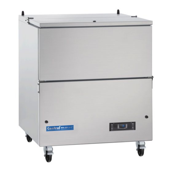
- Page 1 MILK COOLERS Service, Installation and Care Manual 69K-143 69K-145 69K-144 IMPORTANT INFORMATION PLEASE READ CARFEULLY...
-
Page 2: Table Of Contents
Service and Installation Manual CONTENTS SERIAL NUMBER INFORMATION… ..........................3 RECEIVING AND INSPECTING THE EQUIPMENT ....................3 COMMERICAL REFRIGERATION SAFETY & WARNINGS ..................4 SPECIFICATIONS ........................6 CONGRATULATIONS ON YOUR NEW COOLER ............6 INSTALLATION ........................6-7 ELECTRICAL CONNECTION… ..................... 7 FOOD STORAGE. -
Page 3: Serial Number Information
Service and Installation Manual SERIAL NUMBER INFORMATION The serial number of the milk cooler is located inside the unit on the left-hand side near the top on the wall. Always have the serial number of your unit available when calling for parts or service. Also, retain proof of purchase including the order date or your warranty will be voided. -
Page 4: Commerical Refrigeration Safety & Warnings
Service and Installation Manual COMMERCIAL REFRIGERATION SAFETY Your safety and the safety of others are very important. We will provide important safety messages in this manual and on your appliance. Always read and obey all safety messages. Our product instructions will be uploaded on our company website. This is the Safety Alert Symbol. - Page 5 Service and Installation Manual WARNING The appliance uses flammable insulation blowing gas C5H10, disposal of the appliance must be in accordance with the regulations of local authorities regarding flammable items. CAUTION – Risk of Fire or Explosion due to Flammable Refrigerant Used. Follow Handling Instructions Carefully in Compliance with U.S.
-
Page 6: Specifications
Service and Installation Manual SPECIFICATIONS STORAGE CAPACITY CAPACITY CHARGE NEMA MODEL# V/Hz/Ph CAPACITY (13”x13”x11” (19”x13”x11” REFRIGERANT DRAW PLUG Cu-ft Crates) Crates) 69K-143 115/60/1 13.2 3.17 R290A 5-15P 69K-144 115/60/1 19.6 3.17 R290A 5-15P 69K-145 115/60/1 23.5 3.17 R290A 5-15P CONGRATULATIONS ON YOUR NEW COOLER Note these instructions apply to all milk coolers. -
Page 7: Electrical Connection
Service and Installation Manual ELECTRICAL CONNECTION The cooler must be connected to a NEMA 5-15 or 5-20 receptacle with the correct voltage/frequency, as show on the nameplate. The standard for U.S is 115V/60Hz. Voltage variations of ±10% are acceptable. Greater variations can damage the cooler, and in such cases the factory warranty is not valid. In the case of extreme voltage variation, above or below the standard, your local supplier or utility company will be able to advise you, what to do. - Page 8 Service and Installation Manual SOLID STATE THERMOSTAT DESCRIPTIONS 1. FRONT PANEL COMMANDS To display target set point; in programming mode it selects a parameter or confirms an operation. To start a manual defrost To view the latest alarm occurrence; in programming mode it browses the parameter codes or increases the display value To view the latest alarm occurrence;...
-
Page 9: Maintenance
Service and Installation Manual Hold the keys together for more than 3s, till the “POF” message is displayed. 3. ALARM SIGNALS HOW TO SEE THE ALARM AND RESET THE RECORDED ALARM 1. Hold the key to display the alarm signals. 2. - Page 10 Service and Installation Manual needed Never use a high-pressure water wash for this cleaning procedure as water can damage the electrical components located near or at the condenser coil. DANGER MAINTENANCE 1.3 CLEAN THE GASKET - The door gasket should be cleaned frequently to maintain proper sealing 1.4 CHECK AFTER CLEANING - Check the unit again for safety - Check that the unit is operating properly...
-
Page 11: Troubleshooting
Service and Installation Manual TROUBLE SHOOTING SYMPTOMS CAUSES SOLUTIONS The unit is freezing The temperature is set too low to Turn the temperature dial to a maintain safe, read to serve product. warmer setting – allow 2 hours for unit to reach steady state condition and confirm product temperature is within the 34°... -
Page 12: Disposal
Service and Installation Manual DISPOSAL When a worn-out cooler is to be disposed of, this must be done properly. Please be aware of any regulations covering the disposal of such items; there may be special local or state requirements or conditions to be followed. -
Page 13: Exploded View And Parts Listing
Service and Installation Manual EXPLODED VIEW AND PARTS LISTING MODEL: 69K-143 / 69K-144 / 69K-145 Number Description Number Description TOP LID CONDENSER TOP SEAL UNIT BOARD LOCK BRAKE WHEEL DOOR HINGE NORMAL WHEEL DOOR SEAL THERMOSTAT LOCATION KNOB THERMOSTAT BOX... -
Page 14: Wiring/Circuit Diagram
Service and Installation Manual WIRING DIAGRAM MODEL: 69K-143 / 69K-144 / 69K-145... - Page 15 Service and Installation Manual NOTES:...
- Page 16 Service and Installation Manual 7750 Georgetown Road Indianapolis, IN 46268 800-289-3637 • Fax 800-882-0086...
Need help?
Do you have a question about the 69K-143 and is the answer not in the manual?
Questions and answers