Advertisement
Quick Links
Advertisement

Subscribe to Our Youtube Channel
Summary of Contents for Orbit Fitness MAX1
- Page 1 HOME GYM USER MANUAL...
-
Page 2: Parts List Drawing
PARTS LIST DRAWING - 1 -... - Page 3 PARTS LIST DRAWING - 2 -...
- Page 4 PARTS LIST DRAWING - 3 -...
- Page 5 ASSEMBLY INSTRUCTIONS STEP 1 1. Remove two M10X20mm Hex Bolts (90) and two M10 Washers (97) from two Weight Guide Tubes (5). 2. Insert two Weight Guide Tubes (5) into the Rear Base Frame (1), using two M10X20mm Hex Bolts (90) and two M10 Washers (97). 3.
- Page 6 ASSEMBLY INSTRUCTIONS STEP 2 1. Slide nine Weight Plates (39) down two Weight Guide Tubes (5). 2. Slide the Selector Shaft Bushing (52) down the Selector Shaft (22) at First hole fix with the Selector Shaft Pin (53). 3. Insert the Selector Shaft (22) into hole of the Weight Plate (39). 4.
- Page 7 ASSEMBLY INSTRUCTIONS STEP 3 1. Attach two Side Base Frames (6) to the Base Frame (2), using two M10X75mm Hex Bolts (84), four M10 Washers (97) and two M10 Nylon Nuts (101). 2. Slide the Upper Fixed Tube (21) onto the two Weight Guide Tubes (5), using two M8X15mm Hex Bolts (94).
- Page 8 ASSEMBLY INSTRUCTIONS STEP 4 1. Attach the Left and Right Connect Frame (11&12) to the Upper Cross Beam (3), using six Oil Bushings (47), Shaft (81), two M16 Washers (96) and two M16 Nylon Nuts (100). 2. Attach the Press Arm (10) to the Left and Right Connect Frame (11&12), using six Oil Bushings (47), Shaft (81), two M16 Washers (96) and two M16 Nylon Nuts (100).
- Page 9 ASSEMBLY INSTRUCTIONS STEP 5 1. Attach the Arm Bracket (14) to the Support Frame (13), using two M10X65mm Hex Bolts(86), two Washers(¢28X¢10) (104), two M10 Washers (97) and two M10 Nylon Nuts (101). 2. Attach the Arm Bracket (14) to the Main Frame (4), using two M10X70mm Hex Bolts (85), four M10 Washers (97) and two M10 Nylon Nuts (101).
- Page 10 ASSEMBLY INSTRUCTIONS STEP 6 1. Attach the Leg Extension Frame (7) to the Front Support Frame (8), using two Plastic Bushing (¢50X¢11) (45), one M10X75mm Hex Bolt (84), two M10 Washers (97) and one M10 Nylon Nut (101). 2. Insert the Foam Roller Bracket (16) into the Front Support Frame (8), using one Quick Knob (Short) (72).
- Page 11 ASSEMBLY INSTRUCTIONS STEP 7 1. Attach the Seat Cushion (35) to the Seat Frame (17), using two M8X40mm Hex Bolts (92) and two M8 Washers (98). 2. Insert the Seat Frame (17) into the Seat Support Frame (9), using one Quick Knob (short) (72).
- Page 12 ASSEMBLY INSTRUCTIONS - 11 -...
- Page 13 ASSEMBLY INSTRUCTIONS - 12 -...
- Page 14 ASSEMBLY INSTRUCTIONS STEP 8 1.Start with Upper Cable (76) a). With Upper Cable (76) in groove of Pulley (49), thread Upper Cable (76) through Upper Cross Beam (3). b). Install Pulley NO.1 (49) to Upper Cross Beam (3), using one M10X40mm Hex Bolt (88), two M10 Washers (97) and one M10 Nylon Nut (101).
- Page 15 ASSEMBLY INSTRUCTIONS STEP 8 3. Assembly Arm Cable (77) a). Run the end of Arm Cable (77) through Arm (15) and Rotational Pulley Block (18). b). Install Pulley NO.15 (50) to Rotational Pulley Block (18), using one M10X50mm Hex Bolt(87), two M10 Washers (97) and one M10 Nylon Nut (101). c).Insert Steel Bushing (¢10X¢7) (31) into Roller (68), then attach Roller (68) to Rotational Pulley Block (18), using one M6X45mm Hex Bolt (95), two M6 Washers (99) and one M6 Nylon Nuts (103).
- Page 16 ASSEMBLY INSTRUCTIONS STEP 8 1. Insert the U-type Shaft (27) into the both up and down ends of the Safety Cover (65). 2. Attach the Safety Cover (65) to the Lower Fixed Tube (20) and the Upper Fixed Tube (21),and rise the Upper Fixed Tube (21) to tighten the Safety Cover (65), and then M8X15mm Hex Bolts (94) to fix the Upper Fixed Tube (21) on the Weight Guide Tube (5).
-
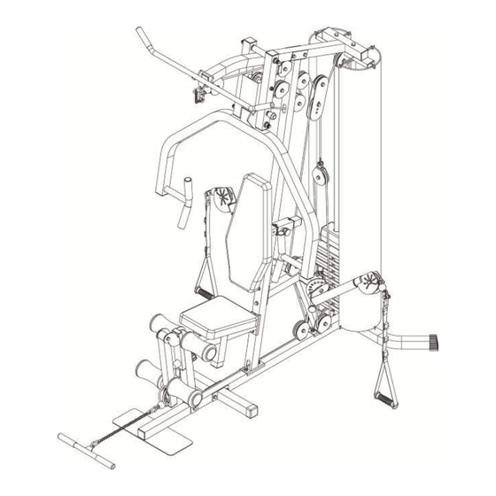
Page 17: Exploded Drawing
EXPLODED DRAWING - 16 -...
Need help?
Do you have a question about the MAX1 and is the answer not in the manual?
Questions and answers