Table of Contents
Advertisement
Advertisement
Table of Contents

Summary of Contents for PHNIX PCF-2.2BD
- Page 1 SWIMMING POOL DEHUMIDIFIER Installation & Operation Manual...
-
Page 3: Table Of Contents
CONTENT 1. Preface Installation Precautions 2.1 Marks 2.2 Icons 2.3 Warnings 2.4 Attention 3. Specifications 3.1 Parameters 3.2 Performance Curve 3.3 Dimensions 3.4 Working Principle 3.5 Product Features 3.6 Hygrostat Control 4. Installation 4.1 Installation Precautions 4.2 Positioning 4.3 Minimum Installation Distances 4.4 Drainage 5.Operation and Usage 5.1.The wire controller operation interface... -
Page 4: Preface
1. Preface Thank you for choosing Swimming Pool Dehumidifier for controlling the climate in you pool area. This product strictly complies with design and production standards to provide perfect performance, high reliability and good adaptability for you. Read the entire manual before the initial start-up of the unit. It is important to know the correct operating procedures for the unit and all safety precautions to prevent the possibility of property damage and/or personal injury. -
Page 5: Installation Precautions
2. Installation Precautions 2.1 Marks Mark Meaning A wrong operation may lead to death or heavy injury on people. WARNING A wrong operation may lead to harm to people or loss of property. ATTENTION 2.2 Icons Icon Meaning Prohibition. What is prohibited will be nearby this icon. Compulsory implement. - Page 6 2. Installation Precautions 2.4 Attention Meaning INSTALLATION Make sure that the basement of the unit is strong enough to avoid any decline or fall down. Fix the unit Make sure that there is circuit breaker for the unit. Lack of circuit breaker can lead to electrical shock or fire.
-
Page 7: Specifications
3. Specifications 3.1 Parameters Swimming Pool Dehumidifier PCF-2.2BD Unit PCF-3.0BD PCF-4.3BD Model Rated Capaclty Dihumidification capacity perday Max pool area Nolse Level dB(A) Rated Voltage/Freq 220-240V~/50Hz Rated Power Input 0.93 1.33 1.97 Rated Running Current Max.Power Input 1.02 1.55 2.28 Max.Running Current... -
Page 8: Performance Curve
3. Specifications 3.2 Performance Curve 80%RH 40%RH 60%RH PCF-2.2BD 80%RH 40%RH 60%RH l / h PCF-3.0BD 80%RH 40%RH 60%RH PCF-4.3BD... -
Page 9: Dimensions
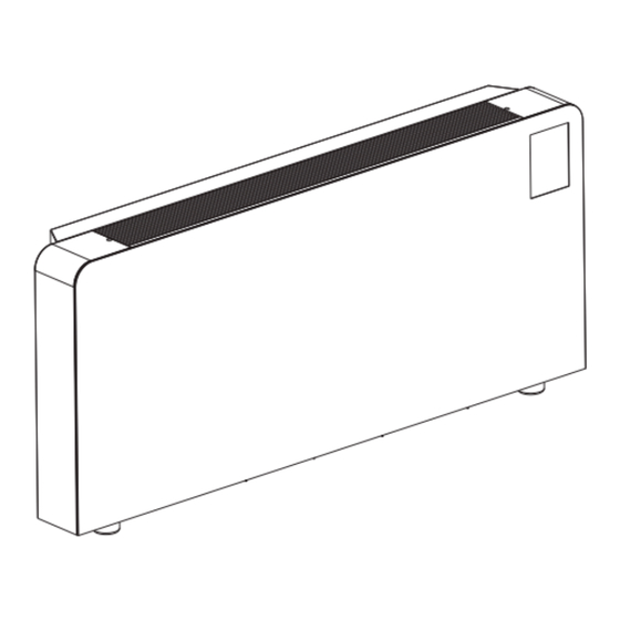
3. Specifications 3.3 Dimensions 3.3.1 Applicable product model:PCF-2.2/3.0/4.3BD Fig.2 PCF-4.3BD PCF-3.0BD PCF-2.2BD Model Length: A 1495 1495 1295 3.4 Working Principle: The unit works by drawing moist air over a refrigerated coil with a small fan. The cold coil of the refrigeration device condenses the water, which is removed, then the air is reheated by the hot coil. -
Page 10: Product Features
3. Specifications 3.5 Product Features 3.5.1 Ultra-low noise With the advanced air ducting technology and the super quiet cross-flow fan, the unit can operate with ultra-low noise. 3.5.2 Ultra-thin casing With the ultra-thin casing of 200mm, which is the result of compact design, the unit can save more space for you when it is compared with the common dehumidifierswith the thickness of 400mm. -
Page 11: Installation
4. Installation 4.1 Installation Precautions 4.1.1 To ensure that the installation is performed correctly and that the appliance will perform perfectly, please carefully follow the instructions indicated in this manual. Fail to respect the rules indicated not only can cause malfunctions of the appliance but also invalidate the warranty, hence our company shall not respond for any damage to persons, animals or property. -
Page 12: Drainage
4. Installation 4.3.3 Wall mounted installation Insert 5 expansion bolts into holes which are bored by φ10 drill and fix the wall suspension bar horizontally(Fig.6). Wall suspension bar Expansion bolt Wall Fig.6 4.4 Drainage Select a suitable size hose to connect to the built-in hose if it is needed(Fig.7). Condensate drainage hose Fig.7 Attention:... -
Page 13: Operation And Usage
Operation and Usage 5.1.The wire controller operation interface 5.1.1 Full display interface Lock symbol Defrost symbol Fault symbol Dehumidification mode Compressor symbol Parameter setting symbol Celsius symbol Main display area Humidity symbol ① ③ ② ④ 5.1.2 Key description Key number Key name Key function Press this key to select the upward option or... -
Page 14: Function Of Wire Controller
Operation and Usage 5.2. Function of wire controller 5.2.1 ON and OFF Off state: press the On/Off key, the unit enters the On state; key lights and display lights are up. On state: press the On/Off key, the unit enters the Off state; key lights and display lights are off . - Page 15 Operation and Usage 5.2.3 wind speed setting In the main interface short press the wind speed button to enter the wind speed setting, wind speed level value flashing Short press the wind speed key, wind speed cycles between 1-3, if no operation in 5s, settings will be saved automatically and return to the main interface. Press the wind speed key If no operation in 5s, settings Press the wind speed...
- Page 16 Operation and Usage 5.2.5 fault interface When the unit fails, the fault code displays in the main display area, press the up or down button, faults will display in cycle. Press the On button to return to the main interface. Press the up or Press the down button to...
-
Page 17: Controller Interface Diagram And Definition
Operation and Usage 5.3. Controller interface diagram and definition FM_DC OP_LED CS1000 COMM_3 TEMP1 TEMP2 RH_1 RH_2 COMP The input and output interfaces of the mainboard are described below. Number Symbol The definition of the ports Power supply zero line Compressor zero line Power line Compressor output port... -
Page 18: Maintenance
6. Maintenance 6.1 Maintenance To guarantee the unit reliable and security operation for a long time, it is suggested to maintain and clean up the unit every six months. . Please take the following steps to clean up the strainer regularly: 1)Press the two red buttons and drag it down slowly(Fig.8);... -
Page 19: Maintenance
6. Maintenance 6.2 Trouble shooting Press the key of "UP" or "Down" to check that if there are more failure codes. You can find solutions to the problems according to the codes. Malfunction Code Reason Solution High pressure protection High pressure protection has appeared 3 times in is too frequently. - Page 20 Code:20170309-0001...
Need help?
Do you have a question about the PCF-2.2BD and is the answer not in the manual?
Questions and answers