Table of Contents
Advertisement
Installation and Operation Manual for Refrigeration Units
Standard cooling
GEKN 600
GEKN 900
GEKN 1200
GEKN 1500
GEKN 2001
GEKN 3001
Riedel refrigeration units, made by Günter
GEK...-D
Unit for Ceiling mounting
The units GEKN 600, 900, 1200, 1500, 2001, and 3001 are suitable for installation in rooms with
a desired temperature range of +12°C to -5°C.
The unit models GEKN 501, 701, 1001, 1201, and 1501, are suitable for installation in rooms
with a desired temperature range of -5°C to -25°C.
with exclusive Bosch service support
GEK...-H /..-S
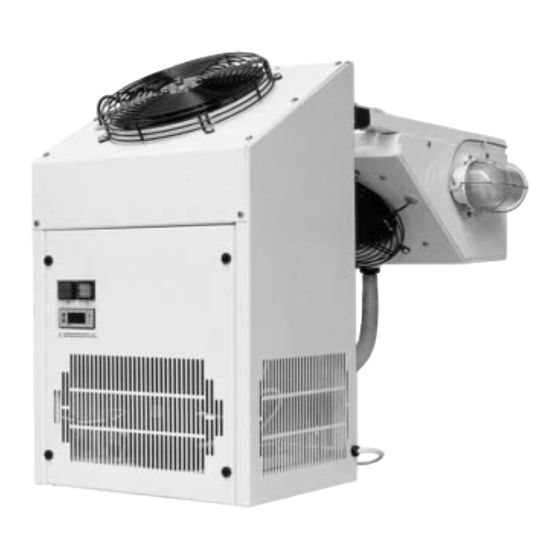
Piggyback / Split model
GEK...-H / ..-W / ..SP
-1-
Extra-low
temperature cooling
GEKT 501
GEKT 701
GEKT 1001
GEKT 1201
GEKT 1501
Status as of 08/2008
Advertisement
Table of Contents

Subscribe to Our Youtube Channel
Related Manuals for Riedel GEKN 600

Summary of Contents for Riedel GEKN 600
- Page 1 Piggyback / Split model GEK...-H / ..-W / ..SP The units GEKN 600, 900, 1200, 1500, 2001, and 3001 are suitable for installation in rooms with a desired temperature range of +12°C to -5°C. The unit models GEKN 501, 701, 1001, 1201, and 1501, are suitable for installation in rooms with a desired temperature range of -5°C to -25°C.
-
Page 2: Table Of Contents
Table of Contents Table of Contents..................................... 2 1) Security instructions and important stipulations.......................... 3 2) Unpacking and handling ................................3 3) Installation information ................................4 4) Initial operation.................................... 6 5) Accessory Connecting Cable For Split Systems.......................... 7 6) Refrigeration controller for standard units........................... 8 7) Refrigeration controller for units with remote control....................... -
Page 3: Security Instructions And Important Stipulations
1) Security instructions and important stipulations For valuable refrigerated goods and/or extended absences, we recommend taking appropriate measures for remote failure indication. Please read the instruction manual carefully before installation and operation. The relevant standards have been upheld and documented in the CE EG-conformity declaration. Disposal of old appliances Worn out units should be immediately rendered unusable. -
Page 4: Installation Information
3) Installation information The installation room must be well ventilated. For usage in ambient temperatures of under 10°C, we recommend a winter controller (optional equipment). For usage in ambient temperatures higher than 35°C, select the "High Temperature Model" (Unit GEK….1). The permissible ambient temperature for this model is 45°C. - Page 5 Installation of evaporation unit Attach the air cooler to the ceiling of the cold storage room. Minimum distances (see dimensions sheet) must be observed. Attention: No condensation evaporation! Condensation water must be fed directly into the drainage system provided by the client. - Based on the direction of air flow, the tubing connectors are found on the right, and the electrical connector on the left (see dimensions sheet): Suggested bore diameter for the refrigerant tubing is 85mm to 95mm.
-
Page 6: Initial Operation
Ceiling installation Create recesses in the cold storage cell ceiling (see Pg. 30 in the instruction manual) and control wall distances. Mount the refrigeration unit. Mount the inner lighting. Attach remote control if desired. Attach the X6 junction box for fault indication (optional), door contact switch (provided by client) and door frame heating (provided by client). -
Page 7: Accessory Connecting Cable For Split Systems
5) Accessory Connecting Cable For Split Systems ACCESSORY CONNECTING CABLE FOR SPLIT SYSTEMS The split unit evaporator and condenser units are wired as pictured in the diagram below. Connecting cable Evaporator cooling cell Condenser Controller Terminal box Switch Switch Legend: S1 cooling room lighting switch X1 clamping strip, terminal box S2 refrigeration switch... -
Page 8: Refrigeration Controller For Standard Units
6) Refrigeration controller for standard units (operation of the unit refrigeration controller TAR 1309) Pos.1 Pos.2 Pos.3 „+“ Button DISPLAY „Programming“ „-“ Button Button Never push the buttons with sharp objects (for example screwdrivers, pens, or similar objects). Display In normal operation, the current cold storage room temperature is shown, which is measured by a sensor. - Page 9 Setting the "upper alarm temperature", parameter P20: Selection and setting as described in parameter P03. The default setting is the given value for P03 plus ..K. The entry can only be made if the code was entered for parameter P30 (see the table for factory settings).
- Page 10 Operational settings of the refrigeration controller TAR 1309 (standard) Changes to the settings of the refrigeration controller should only be performed by a refrigeration specialist. Depending on the unit type - normal cooling (GEKN) or deep-freezing (GEKT) -, the controller is set with the parameter described below. Should you need to adjust these settings, please observe the specified permitted operation parameters P05 and P06 for room temperatures.
-
Page 11: Refrigeration Controller For Units With Remote Control
7) Refrigeration controller for units with remote control (Refrigeration controller TAR 3810) pos.3 pos.1 cooling On-Off „+“ button lighting On-Off DISPLAY „-“ button „select“ button „programming“ button pos.2 pos.4 Do not press the keys with sharp objects (e.g. screwdrivers, pens, or similar). Display In normal operation, the current cold storage room temperature is shown, which is measured by a sensor. - Page 12 Delete alarm signal: push "+" or "-" button Manual defrost activation: push the "P" button and select parameter P49, push "P" button again, push "+" button approx. 3 sec., the defrost process starts and ends automatically. Manual stopping of defrost process: push "-"...
- Page 13 Settings mode of the remote control Attention: The remote control has been pre-configured at the factory. The following parameters from the settings mode should only be changed or adjusted by a refrigeration specialist. By pushing the F-button for approx. 3 sec., one enters remote control settings mode. In remote control settings mode, two light-emitting diodes flash simultaneously.
- Page 14 Operational settings of the refrigeration controller TAR 3810 (remote control) Changes to the settings of the refrigeration controller should only be performed by a refrigeration specialist. Depending on the unit type - normal cooling (GEKN) or deep-freezing (GEKT) -, the controller is set with the below described parameters.
-
Page 15: Technical Data
Operation setting for Parameter Description unit type: GEKN GEKT Alarm mode (0= for alarm exit active) (6= for remote control) Delay time for alarm 90 min. 90 min. Upper alarm temperature P03 + 8 K P03 + 10 K Lower alarm temperature - 6°C - 30°C Command input (0 = deactivated) -
Page 16: Stopping Operation Of The Refrigeration Unit
condensation evaporation with hot gas (saddle model H, wall W and ceiling D) for the unit GEKN 2000-3000, the oil heating in the compressor is standard equipment. The unit comes factory made with tubing according to VBG 20, wired according to VDE regulations, equipped with 2.5 m connecting cable and a shock-proof plug and filled with a hydrocarbon refrigerant. -
Page 17: Causes For Malfunction
Before the cleaning, the unit should be unplugged and secured against any possible start- up. If the air contains fibres, the fins of the heat exchanger will become dirty. To avoid malfunction, the heat exchanger and the tank overflow must be cleaned from time to time. The condenser / evaporator can either be cleaned with a soft brush, with compressed air, or a vacuum cleaner. -
Page 18: Refrigeration Cycle Diagram
13) Refrigeration cycle diagram Legend: 1 Compressor 2 Pressure line 3 High pressure switch 4 Hot gas snake 5 Condenser 6 Receiver dryer 7 Fluid line 8 Expansion valve 9 Evaporator 10 Suction pipe 11 Cooling cell (Insulation for ceiling units) -18-... -
Page 19: Wiring Diagramm
14) Wiring Diagramm Applies to: Piggyback H (operation on unit) SCHALTPLAN FÜR HUCKEPACKGERÄTE Refrigeration controller TAR 1309 (BEDIENUNG AM GERÄT, TAR 1309) Fuse: 16 A (delay) Absicherung 16 A träge -19-... - Page 20 Applies to: Piggyback HF (with remote control) SCHALTPLAN FÜR HUCKE PACKGERÄTE MIT Refrigeration controller TAR 3810 FERNBENDIENUNG(KÜHLSTELLENREGLER TAR 3810) Fuse: 16 A (delay) Option Türkontakt: Option Störmeldung: - Gerät Ein-Aus Brücke 1 entfällt - Parameter 30 auf ,,0'' oder ,,2'' setzen - Licht Ein-Aus Brücke 2+3 entfällt - Brücke 2+3 entfallt - Licht H1 kann nur über Türkontakt...
- Page 21 Applies to: Piggyback H (operation at unit) SCHALTPLAN F ÜR HUCKEPACKGERÄTE BEDIENUNG AM GERÄT Piggyback HF (with remote control) UND FERNBEDIENUNG Legend: remote control sensor, PTC cooling room sensor, PTC evaporator Lege nd : compressor start-up rnbedienung condenser Fühler Kühlraum compressor operating Abtau Fühler condenser...
- Page 22 Applies to: Integrated ceiling unit DF (with remote control) SCHALTPLAN FÜR DECKE NGERÄTE MIT Refrigeration controller TAR 3810 FERNBENDIENUNG(KÜHLSTELLENREGLER TAR 3810) Fuse: 16 A (delay) Option Türkontakt: Option Störmeldung: - Gerät Ein-Aus Brücke 1 entfällt - Parameter 30 auf ,,0'' oder ,,2'' setzen - Licht Ein-Aus Brücke 2+3 entfällt - Brücke 2+3 entfallt - Licht H1 kann nur über Türkontakt...
- Page 23 Applies to: Integrated ceiling unit DF (with remote control) CHALTPLAN F Ü R DECKENGER Ä TE MIT FERNBEDIENUNG Legend: Legen remote control sensor, PTC cooling room Fe nbedienung sensor, PTC evaporator Fühler Kühlraum compressor start-up Abtau Fühler condenser densator Verd ichter Anlauf compressor operating Betriebskondensator Verdichter...
- Page 24 SCHALTPLAN FÜR SPLITGERÄTE Applies to: Split S (operation on unit) (BEDIENUNG AM GERÄT, TAR 1309) Refrigeration controller TAR 1309 Fuse: 16 A (delay) -24-...
- Page 25 Applies to: Split SF (with remote control) SCHALTPLAN FÜR SPLITGERÄTE MIT FER NBENDIENUNG Refrigeration controller TAR 3810 (KÜHLSTELLENREGLER TAR 3810) Fuse: 16 A (delay) Option Türkontakt: Option Störmeldung: - Gerät Ein-Aus Brücke 1 entfällt - Parameter 30 auf ,,0'' oder ,,2'' setzen - Licht Ein-Aus Brücke 2+3 entfällt - Brücke 2+3 entfallt - Licht H1 kann nur über Türkontakt...
- Page 26 Applies to: Split S (operation at unit) HALTPLAN FÜR SPLITGERÄTE Split SF (with remote control) BEDIENUNG AM GERÄT UND FERNBEDIENUNG Legend: remote control sensor, PTC cooling room Legende: sensor, PTC evaporator compresso r start-up Fernbedienung Fühler Kühlraum condenser Abtau ühler compres sor operating Kondensator Verdichter...
-
Page 27: Dimensions Sheets
15) Dimensions sheets Dimensions sheet for unit mounting for piggy-back "-H" and wall installation "-W" Unit models: GEKN 600, 900, 1200, 1500 GEKT 501 Section A-A Section A-A Cell wall recess for wall installation Cell wall recess for saddle installation... - Page 28 Dimensions sheet for unit mounting for piggy-back "-H" and wall installation "-W" Unit models: GEKN 2001 –3001 GEKT 701-1501 Section A-A Section A-A recess in cell wall for wall installation Recess in cell wall for saddle installation Ceiling insulation cooling cell drainage hose for condensate air flow unit GEK...
- Page 29 Dimensions sheet for integrated refrigeration units split-model Unit types: GEKN 600, 900, 1200, 1500 GEKT 501 unit mounting suspension Unit types: GEKN 2001 -3001 GEKT 701-1501 air flow unit mounting suspension Model GEK... b (mm) h (mm) ..N 2001 ..T 701 ..N3001,...
- Page 30 Dimensions sheet for Unit for ceiling mounting Unit types: GEKN 600-DF, 900-DF, 1200-DF, 1500-DF GEKT 501-DF, 701-DF cell ceiling lights remote control air flow Unit types: GEKN 2001-DF, 3001-DF GEKT 1001-DF, 1201-DF 1501-DF recess, cell ceiling cell ceiling lights remote control A = 101 für GEKN...-DF...
-
Page 31: Accessory Tubing For Split Systems
16) Accessory tubing for split systems For split units, the complete connection lines and connection cables must be ordered separately as accessories. It is recommended that this accessory be purchased from your distribution partner. We can supply connecting cables and pre-filled copper tubes up to 10 m in length. -
Page 32: Spare Parts Gek
17) Spare parts GEK..-H,..-S 1. compressor 2. evaporator - block 2.1 evaporator complete 3. defrost heating block 4. drain heating 5. condenser - block To order spare 6. ventilated condenser parts: 7. collector dryer 8. Injection valve 9. refrigeration controller Please list the following (standard)* items when placing a... -
Page 33: Spare Parts Gek
18) SPARE PARTS GEK.. – DF 1. compressor 2. evaporator - block To order spare 2.1 evaporator complete parts: 3. defrost heating 4. drain heating 5. condenser - block Please list the following 6. ventilated condenser items when placing a 7. -
Page 34: Eg - Declaration Of Confrmity
19) EG – Declaration Of Confirmity -34-... -
Page 35: Service
+49 1801 - 33 53 07 As an alternative, you can also call our distribution office during the regular business hours. We will help you with all questions concerning RIEDEL integrated refrigeration units and be happy to transfer the service request to our service partner.
Need help?
Do you have a question about the GEKN 600 and is the answer not in the manual?
Questions and answers