Table of Contents
Advertisement
Quick Links
Product Information
Product Name: Ventilator
Product Model: Boaray 2000C, Boaray 2000D
Version Information
The version number of this user manual may be updated due to the software
upgrades; Shenzhen Prunus Medical Co., Ltd. reserves the right to change it without
giving prior notice.
The version information:
Version No.: M93-P-00224-8.0
Release date: October 2019
I
Advertisement
Table of Contents

Summary of Contents for Shenzhen Prunus Medical Boaray 2000C
- Page 1 Product Model: Boaray 2000C, Boaray 2000D Version Information The version number of this user manual may be updated due to the software upgrades; Shenzhen Prunus Medical Co., Ltd. reserves the right to change it without giving prior notice. The version information: ...
-
Page 2: Ce Mark
CE Mark Well Kang Limited (www.CE-marking.eu) The Black Church, St. Mary's Place, Dublin 7, D07 P4AX, Ireland This product bears a CE mark, as it conforms to European Council Directive for Medical Devices (93/42/EEC), and meets the essential requirements of AnnexⅠof the directive. This product meets the requirements of EN 60601-1-2 standard “Medical electrical equipment - Part 1-2: General requirements for basic safety and essential performance - Collateral Standard: Electromagnetic disturbances - Requirements and tests”. -
Page 3: User's Responsibility
User’s Responsibility Please check the product and accessories firstly when you receive the product, make sure it conforms to the contract. If any damage to the package or the product is found before or after opening the packing case, please contact the local office or the franchiser immediately. -
Page 4: Preface
Preface Description This manual describes the intended use, function, installation, operation and maintenance of the product. Personnel must make themselves familiar with the contents of this manual and the machine’s function before using the apparatus. When you begin to use the ventilator, we consider that you have read the manual carefully. -
Page 5: Table Of Contents
Contents Product Information ........................ I After Service ........................... I Version Information ........................ I CE Mark ..........................II Declaration ..........................II User’s Responsibility ......................III Free Maintenance ......................... III Trademarks ........................... III Preface ..........................IV 1 Safety Information ......................1 ........................2 ARNINGS ........................ - Page 6 2.9.8 Backup ventilation mode ..................28 2.10 ......................28 LARM YSTEM 2.10.1 General description .................... 28 2.10.1.1 Alarm categories...................... 28 2.10.1.2 Alarm priorities......................29 2.10.1.3 Alarm signals ......................29 2.10.1.4 Alarm information and priority .................. 30 2.10.2 Alarm silence ...................... 31 2.10.3 Alarm limit setting ....................
- Page 7 5.8.3 System log ......................60 5.8.4 Biomed ........................ 61 5.8.5 Version information ..................... 61 ..................62 OWER OFF THE VENTILATOR 6. User Maintenance ......................63 ..................64 LEANING AND ISINFECTION ..................... 68 AINTENANCE SCHEDULE ....................69 ENTILATOR SURFACE ...................... 69 XHALATION VALVE ......................
-
Page 8: Safety Information
1 Safety Information The safety information described in this chapter explains unsafe conditions that may occur if not performed correctly according to the manual. Please review all the warning, caution and Note prior to operating the ventilator. This chapter contains important safety information of the ventilator, and some other safety information throughout each chapter of the manual. -
Page 9: Warnings
Warnings Warnings: Boaray2000 series ventilator is a restricted medical device intended for use by qualified, trained personnel. Operations of the equipment should be strictly according to the user manual. Only those conform to the latest IEC 60601-1 standard accessories and auxiliary equipment can be connected to the ventilator. - Page 10 Warnings: material are easy to cause fire. When you detect a burning odor, cut off the oxygen supply device, the power supply and the spare resource immediately. To avoid personnel injury and the risk of electric shock, as well as damage to the ventilator, do not operate the ventilator with its covers or panels removed.
- Page 11 Warnings: damaged. A worn or damaged exhalation valve diaphragm may result in improper patient ventilation. Replace the diaphragm as necessary. If mechanical or electrical problems are found during use, you must stop using the ventilator and contact the qualified service technician for maintenance. Using improperly functioning ventilator may be harmful to the patient.
- Page 12 Warnings: The ventilator shall not be covered or positioned in such a way that the operation or performance of the ventilator is adversely affected. Once any abnormal event occurs, such as the unfamiliar pop-up windows on the screen, unfamiliar sounds, alarms from the patient device, or high priority technology alarm occurs, discontinue use of the ventilator and check it at once, replace the corresponding components as occasion requires.
-
Page 13: Cautions
Cautions Cautions: The ventilator must be serviced and checked at regular intervals by professionals who have received specialized training. Please refer to the chapter 6 for the maintenance time interval information. All service performed on the ventilator should be recorded in a service log in accordance with the regulations. ... - Page 14 Cautions: PRUNUS can be used to be connected to the ventilator system. Otherwise it may cause damage or security to the system. Please refer to the assembling instruction described in the user manual to assemble the system or optional accessories. ...
- Page 15 Cautions: damage the flow sensor. When lifting or moving the ventilator system or some parts of the system, please comply with the instruction of the machine and do some preparation of the safety. Do not use soft tube with the characteristic of antistatic electricity or the electricity conducting.
-
Page 16: Equipment Description
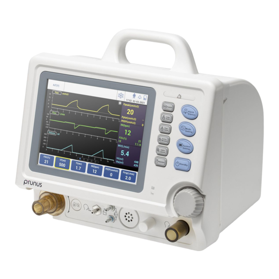
The ventilator should be used only in hospitals or in health care facilities, or during transport of a patient. The Boaray 2000 series ventilator has two models: Boaray 2000D and Boaray 2000C, the differences of their configurations are shown as below:... -
Page 17: Applications
2.1.2 Applications Acute respiratory failure caused by various causes, including respiratory distress syndrome(ARDS). Acute exacerbation of chronic respiratory failure. Severe acute pulmonary edema and persistent asthma. Pediatric cardiac surgery in patients with postoperative ventilation support. The patients with respiratory insufficiency were examined by bronchoscopy, cervical and tracheal surgery, usually with high frequency ventilation support. -
Page 18: Features
2.1.5 Features The ventilator provides following extensive features: Use the touch screen to select the ventilation modes and parameters easily and conveniently. A broad range of operating modes. Electronic PEEP. Accurate ventilation parameters monitoring and display. Clearly audible and visual alarms. Real-time display of waveforms. -
Page 19: External Pipeline Connection Diagram
2.2.1 External pipeline connection diagram Figure 2-1 External pipeline connection view 1. Ventilator main unit 2. Expiratory breathing tube 3. Y piece 4. Flow sensor probe 5. Flow sampling probe 6. Water trap 7. Humidifier 8. Inspiratory breathing tube 9. O supply pipeline 10 Power cable... -
Page 20: Front View
2.2.2 Front view Figure 2-2 Front view 1. Waste gas outlet 2. Expiratory port 3. Expiratory valve rotation indication 4. Expiratory valve unlock button 5. Expiratory label 6. Nebulizer port 7. Flow sensor sampling ports (Up: low pressure, white; 8. Speaker 9. -
Page 21: Rear View
2.2.3 Rear view Figure 2-3 Rear view 3. Label for O inlet, oxygen sensor, 1. Handle 2. Ventilator nameplate and maintenance interfaces 4. O inlet 5. O sensor port (inside cover) 6. Turbine air inlet (inside cover) 7. Air inlet cover 8. -
Page 22: Bottom View
2.2.4 Bottom view Figure 2-4 Bottom view 1. Safety valve filter 2. Bottom fan air intake dust filter Power supply Power supply specification: Input voltage: 100~240Va.c., Frequency: 50/60Hz, Current input: 2A (Max.). Fuse specification: T2AL/250V. AC power indicator: When the ventilator is connected to AC power, the “AC” indicator lights. ... -
Page 23: Battery
2.4 Battery Caution: Exhausted batteries should be disposed according to the local regulations, and cannot be disposed in a normal way. Use an AC power source supply before the internal battery power source is depleted. Only batteries recommended by PRUNUS can be used in the ventilator. ... - Page 24 1. Battery specification The battery can be used as backup power supply in ICU or during transporting patients. The ventilator is equipped with the internal battery. It is recommended that there is always a battery module as backup power supply. The backup battery of the ventilator is rechargeable lithium battery.
-
Page 25: Gas Supply
The indicator is lit whenever the internal battery is proving the primary source of power for the ventilator. The indicator is flashing green when the ventilator is connected to the external AC power and the internal battery is in charging. ... -
Page 26: Membrane Buttons
2.7 Membrane buttons Figure 2-5 Knob and membrane buttons 1. Knob Turn: Switch among the function options, turn it clockwise to increase the parameter value, or anticlockwise to decrease the parameter value. Push: Push down to confirm settings or access menus. Freeze button Press this button to enter freeze status. - Page 27 Expiratory hold button Press this button to enter expiratory hold status after the termination of the current expiratory phase. This status lasts 30 seconds. It extends the patient’s time of expiratory phase manually and prevents the patient from inspiration for this period of time.
- Page 28 System setting button Press this button to access the system setting screen. Mode setting button Press this button to access the mode setting screen. Alarm silence button In the case of an active alarm, press this button to pause the alarm audio of this alarm for 100 seconds.
-
Page 29: Screen Display
2.8 Screen Display The ventilator has a color LCD which can display the parameters and graphics clearly. The main screen of the ventilator is shown as below, for more information about other screens refer to Chapter5 Operations and Settings. Figure 2-6 Main screen Figure 2-7 Main screen area... -
Page 30: Ventilation Modes
Ventilation mode area Display the current ventilation mode. Alarm message display area Display the current alarm message. Status information display area 1) Display the freeze icon. 2) Display the CPAP icon. 3) Display the patient category icon. 4) Display the alarm/alarm silence icon. 5)... -
Page 31: A/C (P) Mode
- 【T 】 - 【T 】 - 【FiO 】 - 【PEEP】 - 【F 】 trig / trig 2.9.2 A/C (P) mode A/C (P), Assist/Control (Pressure), pressure breath with assist ventilation. In A/C (P) mode, the ventilator works at the pre-set inspiratory pressure, respiratory rate, inspiratory time, etc. When the patient triggers the ventilator, the ventilator delivers gases to the patient at the set pressure, inspiratory time, etc. -
Page 32: Spont Mode
SIMV (P) + PS, SIMV (Pressure) + Pressure Support, Pressure breath with SIMV. SIMV (V) + PS, SIMV (Volume) + Pressure Support, Volume breath with SIMV. Different mode determines whether the volume or pressure control ventilation is selected. In SIMV mode, the following parameters need to be set: - 【P 】... -
Page 33: Prvc Mode
- 【T 】 apnea Users can set the backup ventilation in the SPONT mode, providing the mandatory ventilation when the patient is asphyxial. Please refer to section 2.9.8 Backup ventilation mode for more information. 2.9.5 PRVC mode PRVC (Pressure Regulated Volume Control). In PRVC mode, inspiration is accomplished at the pre-set tidal volume and respiratory rate within the pre-set inspiratory time, each inspiration is automatically adapt to the controlled inspiratory pressure, which changes the characteristic of the lung or thoracic to ensure using of the minimum pressure to deliver the pre-set tidal volume and minute volume. -
Page 34: Dualpap Mode
In CPAP mode, the following parameters need to be set: - 【FiO 】 - 【PEEP】 - 【F 】 trig trig - 【T 】 apnea Users can set the backup ventilation in the CPAP mode, providing the mandatory ventilation when the patient is asphyxial. -
Page 35: Backup Ventilation Mode
2.9.8 Backup ventilation mode In SPONT and CPAP modes, when the patient’s apnea time reaches the pre-set value, the apnea alarm condition occurs and the ventilator automatically switches to a predetermined ventilation mode that generate controlled breaths based on the backup ventilation mode and parameters. The backup ventilation mode provides A/C (V) and A/C (P) modes. -
Page 36: Alarm Priorities
2.10.1.2 Alarm priorities According to importance of alarms, the ventilator alarms are grouped into three categories: High priority, Medium priority and Low priority. 1. High priority When high priority alarms occur, the patient’s life may be threatening, or the equipment may fail to work, require immediate action. -
Page 37: Alarm Information And Priority
2.10.1.4 Alarm information and priority Alarm type Message Alarm priority Tidal Volume Low Medium Minute Volume High Medium Minute Volume Low Medium Frequency High Frequency Low Concentration High Medium Physiological alarm Concentration Low High Airway Pressure High High Airway Pressure Low High High Continues Pressure High... -
Page 38: Alarm Silence
Note: When different priorities of alarms occur simultaneously, the alarm indicator and alarm tone will show the characteristic of the alarm with the highest priority. If high priority alarms and medium priority alarms occur simultaneously, the alarm indicator light flashes in red. -
Page 39: Alarm Limit Setting
except the alarm audio. If a new alarm is triggered in the alarm audio paused status, this status will be cancelled and alarm tones will be restored according to this alarm. The 【Alarm silence】button is invalid if no alarm occurs. 2.10.3 Alarm limit setting Refer to section 5.9.2 Alarm setting for the detailed operations of alarm limit setting. -
Page 40: Disassembling And Assembling
3 Disassembling and assembling Battery module 1. Assembling Please assembly the battery module as per the following: 1) As the figure shown below, remove the battery cover on the rear of the main unit, insert the battery module. 2) Put the battery cover back. 3)... - Page 41 Figure 3-2. Remove air inlet cover view As shown in the below figure, screw down the new oxygen sensor clockwise, and then plug the oxygen sensor connection wire into the oxygen sensor interface. After replacement is completed, install the air inlet cover and baffle, and then tighten the screw. Figure 3-3.
- Page 42 Figure 3-5. Remove air inlet cover view 5) Unplug the oxygen sensor connection wire, then remove the oxygen sensor by turning it anticlockwise, as shown below: Figure 3-6. Oxygen sensor disassembly view...
-
Page 43: Patient System
3.3 Patient system 1. Assembling Figure 3-7. Patient system connection view Connect the patient system as the figure shown above. 1. Patient pipeline 2. Y-piece 3. Blue silicon hose 4. White silicon hose 5. Flow sensor probe 6. Snake-shaped tube 7. -
Page 44: Exhalation Valve
pipeline, and avoid the distortion of connectors. It is attached to patient end while connecting nebulizer, otherwise it will impact on VT value. The connection methods refer as the above picture. When sampling hose connected, the colors of white silicon hose and blue silicon hose should correspond with the colors of main unit’s port and flow sensor sampling probe. - Page 45 Figure 3-9. Exhalation valve installation view II 2. Disassembling 1) Before disassembling, Press “ ” button to unlock. Figure 3-10. Exhalation valve disassembly view I 2) Gently rotate the Y-piece clockwise and put out it by your hands, and then take off the exhalation diaphragm.
-
Page 46: Gas Supply
3.5 Gas supply 1. Assembling Figure 3-12. Gas supply connection view Cut off the oxygen supply, and then use a monkey wrench or a special wrench to screw down the oxygen supply connection pipeline①. 2. Disassembling Cut off the oxygen supply, and then use a monkey wrench or a special wrench to remove the oxygen supply connection pipeline. - Page 47 The humidifier connection diagram is as below: Figure 3-13. Humidifier connection diagram The preparation before start-up: Fasten the humidifier by the bracket of the ventilator, pay attention that the location of the humidifier must be lower than the patient. Put the humidifier water container on the front block-ring, press down the front block-ring and slide backwards to the heated plate, when it is in place, the heated plate under the humidifier water container is close to the heating plate and locked automatically, the front block-ring automatically bounces.
- Page 48 Water quality requirement: should use the distilled water, otherwise, it will affect the life of the device. When the temperature inside the heating plate reaches to 92±5°C, the overheated protective relay will disconnect the humidifier power supply, the power indicator light turns off, when it is cooling, the overheated protective relay will reset automatically and connected to the power supply, the power indicator light turns on.
-
Page 49: Pre-Use Check
4 Pre-use check 4.1 System check Before using the ventilator, please read and understand the operations and maintenance of each part of the equipment, and make sure the equipment meets the following requirements. The equipment is in good condition and with no damage. All the components are connected correctly. -
Page 50: Function Check
Function check Caution: If the ventilator fails any tests, remove it from clinical use. Do not use the ventilator until necessary repairs are completed and the tests have passed. Before running function check, disconnect the patient from the equipment and ensure that a backup ventilation mode is available for patient ventilation. - Page 51 System check items include: Alarm signals Blower Inspiratory flow sensor Stop valve Safety valve Pressure sensors Expiration valve Oxygen supply Oxygen sensor 10. Leakage and compliance 11. Proximial flow sensor After the function check has been completed, total results are listed below: : this item successfully passes the test.
-
Page 52: Alarm Test
4.3 Alarm test 4.3.1 Pre-test preparations Connect the test lung to the patient port of the Y-piece. Turn on the system switch. Set parameters of the ventilator as below: Patient category: Adult Ventilation mode: A/C(V) Tidal volume: 450mL ... -
Page 53: Concentration Low Alarm
Make sure the 【Tidal Volume Low】alarm disappears. 4.3.4 O concentration low alarm Press the 【System Setting】 membrane button to access system setting screen. Select 【Alarm Setting】 and confirm. Set the lower limit of FiO alarm more than the monitored value. Make sure the 【O Concentration Low】appears in the alarm message display area. -
Page 54: Tube Partial Occlusion Alarm
4.3.8 Tube partial occlusion alarm Squeeze the inspiratory or expiratory breathing tube using your hand. Verify that the 【Tube partial occlusion】 alarm is activated. Release your hand and verify this alarm is reset automatically. 4.3.9 Oxygen supply pressure low alarm Set FiO to more than 21%, for example 30%。... -
Page 55: Operations And Settings
5 Operations and Settings Keys Different colours of the keys indicate different status. - Blue key (no border): indicates the normal status. You can select or active this key parameter by using the knob or touching this key. - Blue key (yellow border): indicates the selected status. You can adjust this key parameter by using the knob or touching this key. -
Page 56: Boot Self-Test
Boot self-test Warnings: If abnormal alarms occur when the system starts up, do not use the equipment, contact the authorized serviceman or the after service department of PRUNUS. Only the specified, protective grounded power supply can be used in this equipment. 1. -
Page 57: Patient Setting
In the standby screen, users can: - Select the patient category: Adult, Pediatric, and Previous Patient. - Set patient weight. - Start ventilation to enter work mode. - Perform function check. Note: In the standby screen, only technical alarms can be activated, physiological alarm is invalid, but it’s possible to edit the ventilation mode settings and system settings by pressing the corresponding buttons. -
Page 58: Standby
confirm setting. 2. Weight setting You can set the patient’s weight in this screen. The system calculates the referenced tidal volume value in the volume ventilation mode according to different weight of the patient. For different patient categories, the setting range of the weight is different, the allowed range is: - Adult: 20-150kg - Pediatric: 5-20kg. -
Page 59: Main Screen
- 【Freeze】 - 【Inspiratory Hold】 - 【Expiratory Hold】 - 【Extra Breath】 - 【100% O 2 mins】 - 【Nebulizer】 Main screen The Main screen provides the operator with displays of current mode of ventilation, alarm status, battery charge status, monitored parameters, waveforms display and so on. It’s shown as below. - Page 60 Slide” ” to enter the next page, which displays both the wave and loop shown as below. Figure 5-4. Main screen - waveform + loop The loop graphs will display on the right side of the screen. There are three loop options: P-V(Pressure-Volume), F-P (Flow-Pressure), and F-V (Flow-Volume).
- Page 61 shown as below. Figure 5-6. Main screen-measured values Slide” ” to enter the next page shown as below. Figure 5-7. Main screen-reference loop The ventilator system provides three loop options: P- V (Pressure -Volume), F-P (Flow-Pressure), and F-V (Flow-Volume). Select the 【P-V】 button to switch between the loop options. ...
-
Page 62: Mode Setting
Mode setting To access the Mode Setting screen press the 【Mode Setting】 membrane button or touch the current ventilation mode name on the top-left corner of the main screen such as A/C(V), shown as below. Figure 5-8. Mode Setting screen In mode setting screen, the user can perform the following settings: Ventilation mode setting ... - Page 63 settings. 3) Move the focus until the “Accept” key is highlighted, and then push the knob, the ventilator will save your settings and exit the mode setting screen. When a ventilation mode is set, the mode name will display on the top left of the screen. The following ventilation modes are available: Mode Names Description...
- Page 64 3. Auxiliary settings In any mode, touch or highlight the Auxiliary settings and push the knob to display the Auxiliary settings screen shown as below. Figure 5-10. Auxiliary settings screen In Auxiliary Settings screen, the user can set the following: Sigh Touch to select “Close”...
-
Page 65: System Settings
Flow support Touch to open or close the flow support function. System settings Press the 【System settings】 membrane button to access the system settings screen, shown as below. Figure 5-11. System settings screen The system settings screen contains the following items: General settings Alarm settings System log... -
Page 66: Alarm Setting
Figure 5-12. General settings screen In General settings screen, the user can set the following: System Language: Chinese, English Day or night mode: Day, Night Datetime: Date, Time Waveform Selection: Wave1, Wave2 Set the above settings according to the following procedures: Touch or rotate the knob to select or adjust the parameters, and then push the knob. -
Page 67: System Log
To set the alarm limits: Touch the alarm limit or rotate the knob to highlight the alarm limit and push the knob. Rotate the knob to adjust the value. Push the knob to confirm your settings. To adjust the alarm volume, use the “Alarm Volume”. It has five levels, ranging from 20 to 100. Default is Touch “Default”... -
Page 68: Biomed
5.8.4 Biomed The Biomed function is mainly used by trained engineers of Prunus to restore the system to its factory defaults, calibrate, test or upgrade the system. To enter the Biomed screen, go to the Standby mode and then the System Settings screen, touch 【Biomed】 button, then input password and touch 【OK】 button. -
Page 69: Power Off The Ventilator
Power off the ventilator When you finish operating the ventilator, perform the following procedures to power off the ventilator: 1. Press the 【Standby】 button and then the knob to enter the standby mode. 2. Disconnect the breathing tubes from the patient. 3. -
Page 70: User Maintenance
6. User Maintenance Warning: Everyone should realize that some components of the ventilator may be in danger of infection when being dismantled and cleaned. Cautions: Some parts of the equipment cannot be disposed in a normal way. Do not submerge the ventilator or pour cleaning liquids over, into or onto the ventilator. ... -
Page 71: Cleaning And Disinfection
already proven in this user manual, specific equipment and steps. Other methods may be just as effectively, but we do not guarantee unless PRUNUS provides written authorization. When cleaning or sterilizing, use drinking water at least or more healthful water, otherwise, the result may be affected. - Page 72 To avoid sticky residuals, do not use talc, zinc stearate, calcium carbonate, corn starch, or equivalent materials. These materials can go into the patient's lungs and airways and cause irritation or injury. Cautions: To prevent patient exposure to disinfection agents and to prevent premature deterioration of parts, use the cleaning and disinfection methods and agents recommended in this section.
- Page 73 Parts marked 134°C are autoclavable. Recommended temperature is 134ºC. By using autoclave to increase vapor pressure, the temperature also increases, rapidly solidifying bacterioprotein. The disinfection effect of this method is fast and reliable. Some of the ventilator’s parts can be cleaned and disinfected. Different parts of the ventilator should be disinfected using different methods.
- Page 74 Cleaning Disinfection Recommended frequency Parts ① ② Ultraviolet Interval Wipe Immersion Wipe Immersion Autoclaving radiation Ventilator expiration valve assembly Expiration valve Each ② B or C membrane (silicone) patient/weekly Expiration valve Each assembly (except ② B or C patient/weekly membrane) Ventilator patient tubing (reusable) Patient tubing Each...
-
Page 75: Maintenance Schedule
Cleaning Disinfection Recommended frequency Parts ① ② Ultraviolet Interval Wipe Immersion Wipe Immersion Autoclaving radiation (recommended time). Then clean with water and dry completely. C: Steam autoclave at 134ºC for 10 to 20 minutes (recommended time). D: Ultraviolet radiation for 30 to 60 minutes (recommended time). As necessary*: shorten the cleaning and disinfection intervals if the equipment is used in dusty environment to ensure that the equipment surface is not covered by dust. -
Page 76: Ventilator Surface
Maintenance Maintenance frequency Check the parts for damage, When cleaning and installing replace or repair if necessary Ventilator surface 1、 Using a damp cloth soaked in a cleanser (like 75% of medical alcohol) to wipe the ventilator surface. 2、 Using a dry lint-free cloth to clean the residual detergent on the surface. Warning: ... -
Page 77: Breathing Tubes
valve, do not let liquid spatter into the exhalation valve openings. 3. Let the Y-piece and diaphragm soak for 30 minutes in chemical disinfectant (such as 2% glutaraldehyde solution). 4. Take them out and soak for 30 minutes in clean water, and repeat twice. 5. -
Page 78: Oxygen Sensor
Cautions: The battery can only be charged by this ventilator. Note: Use the battery at least once every month to extend its lives. Charge the battery before it is depleted. Inspect and replace battery regularly. Battery life depends on how frequent and how long battery is used. -
Page 79: Turbine Air Inlet Dust Filter
Turbine air inlet dust filter 1. Refer to section 3.2 Oxygen sensor to disassemble the air inlet cover with turbine air inlet dust filter. 2. Immerse the air inlet cover in the water and clean it. 3. Wipe off the remaining water with a dry lint-free cloth. 4. -
Page 80: Appendix A Working Principle
Appendix A Working Principle A.1 Pneumatic circuit principle Boaray2000 is an electrically powered ventilator, the system consists of the O supply and control modules, air and O mixer module, turbine control inhalation module, exhalation control module, nebulizer and patient system. The modules figure is as shown below. -
Page 81: Pneumatic Circuit Diagram
5. Nebulizer module—Flow requirement: 7L/min. 6. Patient system—To achieve the purpose of mechanical ventilation. A.2 Pneumatic Circuit Diagram Appendix A-2. Pneumatic circuit diagram Parts list is shown in the following table: A1/A2/A3 Filter I1/I2 Check valve Pipeline pressure sensor B2/B3/B4 Pressure sensor sensor Pressure regulator... -
Page 82: Appendix B Product Specifications
Appendix B Product Specifications This ventilator complies with the following standards. EN 60601-1/IEC60601-1 Medical electrical equipment Part I: General requirements for safety EN 60601-1-2 Medical electrical equipment -Part1-2: General Requirements for Safety- Collateral standard: Electromagnetic compatibility-Requirements and tests. EN ISO 80601-2-12 Medical electrical equipment Part 2: Particular requirements for ... -
Page 83: Technical Parameters
Technical parameters Parameters Description Product weight 7.5 kg (Net weight) Dimension 311 x 304 x 292 (W x H x D) Category Electrically powered ventilator. Display 8.4 inch TFT display. 120 minutes at least and up to 240 minutes when powered by a Battery fully-charged battery in the standard work state) A/C(P), A/C(V), SIMV(P)+PS, SIMV(V)+PS, PRVC, SPONT, CPAP,... -
Page 84: Setting Parameters
Setting parameters Parameters Description Accurancy Range: 20~2000mL(Boaray2000D) Range: 50~2000mL(Boaray2000C) ±20mL, or ±15% of the Tidal volume Increment: 20~100mL: 5mL set value, whichever is 100~1000mL: 10mL greater 1000~2000mL: 50mL Range: 4~100bpm, increment: 1bpm. ±2bpm or ±10% of the set Respiratory rate value, whichever Range: 1~40, increment: 1bpm. -
Page 85: Monitoring Parameters
Monitoring parameters Parameters Description Inspiratory tidal volume Range: 0~2500mL, Resolution: 1mL. Expiratory tidal volume Range: 0~2500mL, Resolution: 1mL. Minute ventilation volume Range: 0~50L, Resolution: 0.1L/min. Spontaneous minute Range: 0~50L, Resolution: 0.1L/min. ventilation volume Total respiratory rate Range: 0~100bpm, Resolution: 1bpm. Spontaneous respiratory rate Range: 0~99bpm, Resolution: 1bpm. -
Page 86: Alarm Setting Parameters
Alarm setting parameters Alarms Ranges OFF, 10~1500mL Increment: 10~100 mL: 10mL Tidal volume Lower limit 100~500 mL: 20mL 500~1500 mL: 50mL 1~40 L/min, OFF Upper limit Increment: 1 L/min Minute ventilatin volume OFF, 0~39 L/min Lower limit Increment: 1 L/min 21~100% Upper limit Increment: 1%... -
Page 87: Appendix C Alarms
Appendix C Alarms High priority alarms Alarms Possible reasons Solutions apnea time exceeds pre-set value or alarm limit. Check the patient and breathing Apnea The Interval between the two system. continuous inhalation tries exceed Check the ventilation settings. the set alarm limit. The airway pressure exceeds the upper limit of pre-set pressure. - Page 88 Alarms Possible reasons Solutions failutes. settings. expiratory sensor Check the heating wire of the disconnected. humidifier (if fitted). The expiratory sensor probe is Check pipeline connections and blocked. expiratory sensor probe There is accumulated water in the connections. sampling line of the expiratory sensor probe.
-
Page 89: Medium Priority Alarms
Medium priority alarms Alarms Possible reasons Solutions The minute volume exceeds the pre-set Check patient and breathing system. Minute ventilaton volume or default alarm limit. Check the trigger sensitivity setting. volume high ventilator triggers Check the alarm limit settings. automatically.(auto-circle) The minute ventilation volume exceeds the Check patient and breathing system. -
Page 90: Low Priority Alarms
Low priority alarms Alarms Possible reasons Solutions The respiratory frequency is too Check and take care of the patient. high. Check the trigger settings. Frequency high Automatically triggering. Check the connection of the patient Leakage of the pipeline. pipeline. The respiratory frequency is too Check and take care of the patient. -
Page 91: Appendix D Emc
Appendix D EMC Cautions: The ventilator meets the requirement of electromagnetic compatibility in EN 60601-1-2. The user needs to install and use according to electromagnetism compatibility information which is attached with it. Portable and mobile RF communication devices may influence the ventilator’s performance, so it should be kept away from them during using. - Page 92 Guidance and manufacturer’s declaration – electromagnetic emission – for all EQUIPMENT AND SYSTEMS Guidance and manufacturer’s declaration – electromagnetic emission The ventilator is intended for use in the electromagnetic environment specified below. The customer or the user of ventilator should assure that it is used in such an environment. Emissions test Compliance Electromagnetic environment - guidance...
- Page 93 Guidance and manufacturer's declaration – electromagnetic immunity – for all EQUIPMENT and SYSTEMS Guidance and manufacturer’s declaration – electromagnetic immunity The ventilator is intended for use in the electromagnetic environment specified below. The customer or the user of the ventilator should assure that it is used in such an environment. Immunity test IEC 60601 Compliance level...
- Page 94 IEC 61000-4-11 70 % U 70 % U operation during power (30 % dip in U (30 % dip in U mains interruptions, it is for 25 cycles for 25 cycles recommended that the < 5 % U < 5 % U ventilator be powered (>95 % dip in U (>95 % dip in U...
- Page 95 Guidance and manufacturer’s declaration – electromagnetic immunity Guidance and manufacturer’s declaration – electromagnetic immunity The ventilator is intended for use in the electromagnetic environment specified below. The customer or the user of the ventilator should assure that it is used in such an environment. Immunity test IEC 60601 test level Compliance...
- Page 96 output power rating of the transmitter in watts (W) according to the transmitter manufacturer and d is the recommended separation distance in metres (m). Field strengths from fixed RF transmitters, as determined by an electromagnetic site survey, should be less than the compliance level in each frequency range.
- Page 97 Field strengths from fixed transmitters, such as base stations for radio (cellular/cordless) telephones and land mobile radios, amateur radio, AM and FM radio broadcast and TV broadcast cannot be predicted theoretically with accuracy. To assess the electromagnetic environment due to fixed RF transmitters, an electromagnetic site survey should be considered.
- Page 98 Recommended separation distances between portable and mobile RF communications equipment and the EQUIPMENT or SYSTEM Recommended separation distances between portable and mobile RF communications equipment and the ventilator The ventilator is intended for use in an electromagnetic environment in which radiated RF disturbances are controlled.
-
Page 99: Appendix E Glossary And Symbols
Appendix E Glossary and Symbols E.1 Glossary Abbreviation/Glossary Definition A/C (V) Volume - Assist/control ventilation. A/C (P) Pressure - Assist/control ventilation. SIMV Synchronized intermittent mandatory ventilation. Synchronized intermittent mandatory ventilation (Pressure SIMV (P) + PS control) + Pressure support Synchronized intermittent mandatory ventilation (Volume SIMV (V) + PS control) + Pressure support DualPAP... - Page 100 Abbreviation/Glossary Definition Support pressure of low pressure level, unit: cmH Airway peak pressure, unit: cmH peak Mean airway pressure, unit: cmH mean Inspiratory plateau pressure, unit: cmH plat Minimum airway pressure, unit: cmH Expiratory sensitivity, unit: %. concentration, unit: %. Airway resistance, unit: cmH O/(L/s).
-
Page 101: Symbols
E.2 Symbols Consult instructions for use Alarm icon Alarm silence icon Freeze button Inspiratory hold button Expiratory hold button Extra breath button 100% O 2mins button Nebulizer button Alarm silence button Ventilation setting button System setting button Waveform freeze Standby button countdown icon Spontaneous breath icon Nebulization label... - Page 102 Flow sensor sampling line AC indicator label Battery indicator Inspiratory label Exhalation valve unlock Expiratory label label supply connector Oxygen sensor label USB port Serial port Ethernet interface Fuse Date of manufacture Manufacturer System switch label Serial number :On; :Off Authorized representative in the EUROPEAN COMMUNITY This symbol indicates TYPE B equipment according to the EN60601-1 standard.
-
Page 103: Package Symbols
The exhausted batteries should not be disposed in a normal way. In some areas, there may be no recycle facilities Proper disposal of products E.3 Package symbols THIS WAY UP FRAGILE DO NOT ROLL KEEP AWAY FROM RAIN KEEP AWAY FROM STACK LIMIT BY NUMBER SUNLIGHT... -
Page 104: Appendix F Default Settings
Appendix F Default settings The table below lists the default settings when the ventilator left the factory, user can reset the parameters when necessary. Power on default settings Patient category Adult Pediatric Ventilation mode A/C(V) A/C(V) Ventilation parameters default settings Parameter items Adult Pediatric... - Page 105 Alarm default settings Lower limit: OFF Upper limit: Adult: 40/ Pediatric:20 Paw (cmH Lower limit: 0 Upper limit: / Oxygen supply (kPa) Lower limit: 280 Alarm volume...
Need help?
Do you have a question about the Boaray 2000C and is the answer not in the manual?
Questions and answers