
Related Manuals for Carbide 3D Shapeoko HDZ 4.0

Summary of Contents for Carbide 3D Shapeoko HDZ 4.0
- Page 1 HDZ 4.0 ASSEMBLY GUIDE support@carbide3d.com docs.carbide3d.com 07/13/2020 Version 4.0...
-
Page 2: Prior To Installation
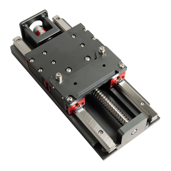
Introduction If you encounter any issues during assembly, please contact us at: support@carbide3d.com This assembly process is uniform for the Shapeoko 3, 3XL, and 3XXL. The installation process is also the same across all HDZ units. Prior to Installation Before you assemble or install the HDZ, check the rotation of the ball screw. To test, stand the HDZ on end, grasp the sides with both hands, and press down on the top of the Z-carriage plate with both thumbs. - Page 3 Inventory HDZ Kit Contents The HDZ comes with the components listed in the table below and show in Fig. 1 . Figure 1 Item Description HDZ (Heavy-Duty Z/X Carriage) EZTram Plate M5 x 18mm Socket Head Cap Screw M5 x 10mm Button Head Cap Screw HD Eccentric Spacer (non-threaded) M5 x 25mm Male-Female Threaded Standoff M5 x 10mm Socket Head Cap Screw...
- Page 4 Shapeoko Carryover Components The HDZ utilizes several parts from the existing machine. All components and hardware to be carried over are listed in the table below and shown in Fig. 2 . Throughout this guide, carryover parts will be called out by the words: CARRY OVER .
- Page 5 Disassemble and Remove the Existing X/Z-Carriage NOTE: As you complete the disassembly process, you may find it helpful to keep each carryover component and its associated hardware together and away from the new HDZ parts to avoid any mix ups. Disconnect Cables and the X-Axis Belt 1.
- Page 6 6. Lift the X/Z-carriage away from your Shapeoko. Disassemble the X/Z-Carriage In this section you will remove and CARRY OVER the X-Axis stepper motor , Z-Axis stepper motor , and the router/spindle mount and hardware . You will also remove the motor pulley from the Z-Axis stepper motor drive shaft. Separate the Z-Carriage from the X-Carriage 1.
- Page 7 CARRY OVER the X-motor . 7. Remove the Z-motor (upper motor) from the back of the X-carriage. a. Use a 4mm hex key to remove the M5x10mm SHCS securing the motor. 8. Remove the drive pulley from the Z-motor drive shaft. (The Z-motor has the shorter lead cables.) a.
- Page 8 Assemble and Install the HDZ HDZ Assembly Tips We recommend assembling as much of the HDZ as possible before installing it onto the Shapeoko; this process is described in the steps below. NOTE: The application of a blue (i.e. light/medium grade) thread locker is at your discretion. We suggest adding it post-assembly if any screws happen to work their way loose during use.
- Page 9 Install the Z-Motor and Coupling HDZ kit + Carryover Components: Item Description Z-Motor Shaft Coupling M5 x 10mm Socket Head Cap Screw Z-Motor* [CARRYOVER] *Z-Motor has shorter lead cables and bare drive shaft. 1. Install the Z-motor coupling onto the ball screw at the top of the HDZ.
- Page 10 d. Use a 2.5mm hex key to secure coupling to Z-motor drive shaft. See Fig. 7 . NOTE: Ensure both set screws on the coupling are tight. Failure to do so will lead to slippage. Using a small amount of blue thread lock on the motor shaft and ball screw shaft is acceptable.
- Page 11 support@carbide3d.com docs.carbide3d.com 07/13/2020 Version 4.0...
- Page 12 Install the X-Motor Standoffs HDZ Kit: Item Description M5 x 25mm Male-to- Female Threaded Standoffs 1. Hand-screw the standoffs to the back of the HDZ. See Fig. 9 . a. Do NOT use tools or overtighten the standoffs. b. Screw M5x25mm standoffs into the four evenly-spaced M5 screw holes at center of the Figure 9...
- Page 13 4. Install the bottom two V-wheels on the back of the HDZ. Fig. 11 and 12 . a. Be sure V-wheels are properly seated on lower V-rail. b. Use a 10mm wrench to hold eccentric nuts in the fully open position (dimples up).
- Page 14 Install the X-Motor HDZ Kit + Carryover Components: Item Description M5 x 10mm Socket Head Cap Screw X-Motor [CARRYOVER] 1. Thread the free end of the X-Axis belt under the idlers at the back of the HDZ. 2. Push a large loop up between the idlers. See Fig.
- Page 15 Install the X-Axis Belt Carryover Components: Item Description X-Axis Belt and Hardware: Belt Clip (1), and M5x10mm Socket Head Cap Screw (1) [CARRYOVER] 1. Install and tension the X-Axis belt. See Fig. 15 a. Attach the belt clip to the free end of the belt.
- Page 16 Install the X-Axis Homing Switch Carryover Components: Item Description X-Axis Homing Switch Assembly and Hardware: 1-inch Round Spacers (2), M5x35mm Socket Head Cap Screw (2) [CARRYOVER] 1. Assemble the X-Axis homing switch plate in this order: a. M5x35mm SHCS (2) b.
- Page 17 Install the Z-Axis Homing Switch Carryover Components: Item Description Z-Axis Homing Switch and Hardware: M3x12mm Socket Head Cap Screw (1), and M3 Washer (1) [CARRYOVER] 1. Assemble the Z-Axis homing switch in this order: a. M3x12mm screw b. M3 washer Figure 18 c.
- Page 18 Install the Spindle Mount HDZ Kit + Carryover Components: Item Description EZTram Plate M5 x 18mm Socket Head Cap Screw M5 x 10mm Button Head Cap Screw HD Eccentric Spacer (non- threaded) Spindle/Router Mount [CARRYOVER] M5 x 16mm Button Head Figure 20 Cap Screw [CARRYOVER] 1.
-
Page 19: Maintenance
80mm spindle mount kit. A detailed video on tramming your Shapeoko can be found here: https://www.youtube.com/watch?v=rGOGlNurglE For additional advice on tramming, check out the Carbide 3D community: community.carbide3d.com Maintenance The HDZ is pretty much maintenance-free. We recommend keeping it as dust-free as possible. A quick coat of synthetic grease (such as Mobil Vactra No. -
Page 20: Update Settings
Update the Software Settings WARNING: The HDZ is supported by Carbide Motion 4.17 onwards. Do NOT use an older version of Carbide Motion. Update Settings Download and install Carbide Motion from: https://carbide3d.com/carbidemotion/download/. Confirm all of the homing switches and motors are connected correctly, then, ensure that there is nothing restricting the Shapeoko’s movement. - Page 21 Test Homing Switches As you have disconnected multiple switches it is good practice to test the homing switches. 1. Press each blue homing switch trigger in turn and check to see if it appears in the “GRBL Active Input Pins” section in the Settings window.
- Page 22 Happy milling! support@carbide3d.com docs.carbide3d.com 07/13/2020 Version 4.0...
Need help?
Do you have a question about the Shapeoko HDZ 4.0 and is the answer not in the manual?
Questions and answers