
Summary of Contents for X-FIT X-FIT 7
- Page 1 USER’S MANUAL X-FIT 7 MOTORIZED TREADMILL MODEL NUMBER: X-FIT 7 USER WEIGHT LIMITATION: 136kgs. (300lbs.) SERIAL NUMBER (found on frame): Edition...
- Page 2 X-FIT 7 MOTORIZED TREADMILL PRECAUTIONS Precautions: WARNING: To reduce the risk of burns, fire, electric shock, or injury to persons, read the following important precautions and information before operating the treadmill. It is the responsibility of the owner to ensure that all users of this treadmill are adequately informed of all warnings and precautions.
-
Page 3: Power Requirements
X-FIT 7 MOTORIZED TREADMILL POWER REQUIREMENTS Power Requirements: IMPROPER CONNECTION OF THE EQUIPMENT GROUNDING CONNECTOR CAN RESULT IN A RISK OF AN ELECTRIC SHOCK. CHECK WITH A QUALIFIED ELECTRICIAN OR SERVICE MAN IF YOU ARE IN DOUBT AS TO WHETHER THE PRODUCT IS PROPERLY GROUNDED. DO NOT MODIFY THE PLUG PROVIDED WITH THE PRODUCT, IF IT WILL NOT FIT THE OUTLET;... -
Page 4: Pre-Assembly
X-FIT 7 MOTORIZED TREADMILL PREASSEMBLY Open the boxes: You are now ready to open the boxes of your new equipment. Make sure to inventory all of the parts that are included in the boxes. Check the Hardware Comparison Chart for a full count of the number of parts included for this product to be assembled properly. -
Page 5: Hardware Comparison Chart
X-FIT 7 MOTORIZED TREADMILL HARDWARE COMPARISON CHART Hardware chart: For your convenience, we have identified the hardware used in the assembly of this product. This chart is provided to help you identify those items that may be unfamiliar to you. -
Page 6: Parts List
X-FIT 7 MOTORIZED TREADMILL PARTS LIST DESCRIPTION QTY. ORDER NO. DESCRIPTION QTY. ORDER NO. Console XFIT7-01 Upright Support Lock Pin XFIT7-30 M6 x 15mm Allen Head Top Console Housing XFIT7-02 Screw XFIT7-31 Bottom Console Housing XFIT7-03 Left Upright XFIT7-32 Bottle Bracket... - Page 7 X-FIT 7 MOTORIZED TREADMILL PARTS LIST DESCRIPTION QTY. ORDER NO. DESCRIPTION QTY. ORDER NO. Side Cover - Right XFIT7-57 Clip XFIT7-84 M6 x 15mm Phillip Head Screw XFIT7-58 M10 x 63mm Bolt XFIT7-85 Front Foot Platform XFIT7-59 Front Roller XFIT7-86...
- Page 8 X-FIT 7 MOTORIZED TREADMILL PARTS LIST DESCRIPTION QTY. ORDER NO. DESCRIPTION QTY. ORDER NO. M8 Nylon Nut XFIT7-111 Transformer XFIT7-138 Elevation Support Tube Side Cover - Left XFIT7-112 XFIT7-139 Elevation Support Tube Side Cover - Right XFIT7-113 Rubber Dot XFIT7-140...
-
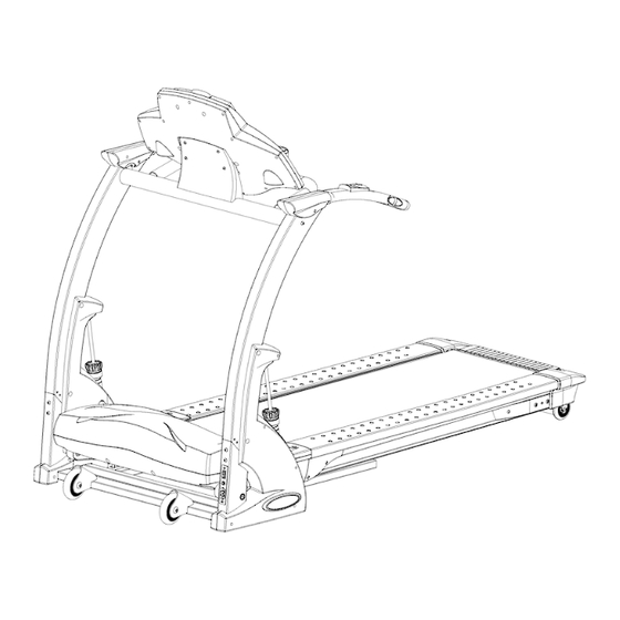
Page 9: Parts Diagram
X-FIT 7 MOTORIZED TREADMILL PARTS DIAGRAM A MAJORITY OF THE PARTS SHOWN HERE HAVE BEEN PREASSEMBLED AT THE FACTORY. - Page 10 X-FIT 7 MOTORIZED TREADMILL PARTS DIAGRAM A MAJORITY OF THE PARTS SHOWN HERE HAVE BEEN PREASSEMBLED AT THE FACTORY.
- Page 11 X-FIT 7 MOTORIZED TREADMILL ASSEMBLY STEP 1: Remove your treadmill from the carton and place it on the floor in an open area as shown in FIG-1. Rotate the Left Upright (32) and Right Upright (33) up to the correct position as shown and secure in place using four M8 x 16mm Allen Bolts (29).
- Page 12 X-FIT 7 MOTORIZED TREADMILL ASSEMBLY STEP 2: Remove the four M6 x 20mm Allen Head Bolts (10) from the back of the Bottom Console Housing (3), they have been preassembled by the factory. Then secure the Bottom Console Housing (3) to the...
- Page 13 X-FIT 7 MOTORIZED TREADMILL ASSEMBLY STEP 3: Attach a Plastic Cover (40) to the Left Upright (32) and to the Right Upright (33) then secure each in place using one M6 x 15mm Phillip Head Screw (58).
- Page 14 X-FIT 7 MOTORIZED TREADMILL ASSEMBLY STEP 4: Attach the Upright Support Tube Assembly (36) to the Left Upright (32) and secure with Upright Support Lock Pin (30) and M6 x 15 Allen Head Screw (31). Repeat the procedure on the Right Upright (33).
- Page 15 X-FIT 7 MOTORIZED TREADMILL ASSEMBLY STEP 5: Rotate up the Suspension System Hardware Assembly (34) and secure to the Left Upright (32) using Bolt (27), Rubber Spacers (28) and Nut (29). Repeat this procedure on the Right Upright (33).
- Page 16 X-FIT 7 MOTORIZED TREADMILL ASSEMBLY STEP 6: Remove the M5 x 12 Screw (12) from the Console Support Tube (11) then rotate the Console Support Tube (11) up to the correct position as shown and secure it in place using the M5 x 12 Screw (12).
- Page 17 X-FIT 7 MOTORIZED TREADMILL ASSEMBLY STEP 7: Attach the Upright Plastic Shroud - Left #1 (52) to the Upright Plastic Shroud - Left #2 (53) and Left Upright (32) using #8 x 25mm Screws (18) and four #8 x 19mm Screws (19).
- Page 18 X-FIT 7 MOTORIZED TREADMILL ASSEMBLY STEP 8: Connect the two sets of wires between the Handlebar (133) and the Left Upright (32) as shown in FIG 5. Attach the Handlebar (133) to the Left Upright (32) using two M8 x 10mm Bolts (13).
- Page 19 X-FIT 7 MOTORIZED TREADMILL ASSEMBLY STEP 9: Attach the Handlebar Rear End Cap - Left #1 (14) and Handlebar Rear End Cap - Left #2 (15) to the top of the Left Upright (32) using two #8 x 25mm Screws...
- Page 20 STEP 11: Attach the Front Handlebar (130) to the Console Support Tube (11) and secure with two M8 x 25mm Bolts (99). Your X-Fit 7 treadmill is now fully assembled. NOTE: Please make sure the Safety Key is inserted (it...
-
Page 21: Stabilizer Adjustment
X-FIT 7 MOTORIZED TREADMILL STABILIZER ADJUSTMENT How to level the treadmill: An uneven floor or improper stabilizer level can cause the treadmill to wobble during use as well as the incline adjustment to function incorrectly. Please follow the procedure described below to make sure the treadmill stabilizer is adjusted correctly prior to use. -
Page 22: Transportation Instructions
X-FIT 7 MOTORIZED TREADMILL TRANSPORTATION INSTRUCTIONS How to transport your treadmill: To move your treadmill simply lift the rear of the deck and roll it to the desired location. -
Page 23: Maintenance
X-FIT 7 MOTORIZED TREADMILL MAINTENANCE How to maintain your treadmill: Proper maintenance is very important to ensure your treadmill is always in top working condition. Improper maintenance could cause damage or shorten the life of your treadmill. • Important: Never use abrasives or solvents to clean the treadmill. To prevent damage to the computer, keep liquids away and keep it out of direct sunlight. - Page 24 X-FIT 7 MOTORIZED TREADMILL MAINTENANCE To apply lubricant to the walking belt: Position the walking belt so that the seam is located on top and in center of the walking board. Insert the spray nozzle into the spray head of the lubricant can.
-
Page 25: Important Steps
X-FIT 7 MOTORIZED TREADMILL IMPORTANT STEPS Warning: Before using this product, please consult your personal physician for a complete physical examination. Frequent and strenuous exercise should be approved by your doctor first. If any discomfort should result from your use of this product, stop exercising and consult your doctor. -
Page 26: Target Heart Rate
X-FIT 7 MOTORIZED TREADMILL TARGET HEART RATE Finding your pulse: To make sure your heart is beating in its target zone, you’ll need to know how to monitor your heart rate. The easiest way is to feel the pulse in the carotid artery on either side of your neck, between the windpipe and the large neck muscles. -
Page 27: Muscle Chart
X-FIT 7 MOTORIZED TREADMILL MUSCLE CHART Targeted muscle groups: The exercise routine that is performed on this product will develop primarily lower body muscle groups. These muscle groups are shown in gray color on the chart below. Shoulder muscles Pectoral muscles... -
Page 28: Stretching Routine
X-FIT 7 MOTORIZED TREADMILL STRETCHING ROUTINE Warm up and cool down: A successful exercise program consists of a warm-up, aerobic exercise, and a cool-down. Do the entire program at least two or three times a week, resting for a day between workouts. After several months, you can increase your workouts to four or five times per week. - Page 29 X-FIT 7 MOTORIZED TREADMILL STRETCHING ROUTINE Hamstring Stretch: Sit with your right leg extended. Rest the sole of your left foot against your right inner thigh. Stretch toward your toe as far as possible. Hold for 15 counts. Relax and then repeat with left leg extended.
- Page 30 Copyright © 2003...
Need help?
Do you have a question about the X-FIT 7 and is the answer not in the manual?
Questions and answers