
Subscribe to Our Youtube Channel
Related Manuals for Hiniker 8160

Summary of Contents for Hiniker 8160
- Page 1 8160 OPERATOR’S MANUAL DO NOT USE OR OPERATE THIS EQUIPMENT UNTIL THIS MANUAL HAS BEEN READ AND THOROUGHLY UNDERSTOOD PART NUMBER 39300030 Rev. E...
-
Page 3: Table Of Contents
TABLE OF CONTENTS TITLE 39300030 Rev. E 12/10 Manual/39300030RevE SAFETY ....................................3 TO THE PURCHASER ................................4 SYSTEM OVERVIEW ...............................5-11 8160 CONSOLE ................................6-11 Switches and Indicators................................6 Boom Switches .................................6 Run/Hold Switch ................................6 Rate Select Switch ................................6 Warning Light ...................................6 Horn ....................................6 Keyboard ....................................7 POWER Key ..................................7... - Page 4 HM860 Flowmeter ..............................49-50 Flow Meter Calibration Test ............................51 Servo Valve ................................52-54 Remote Run/Hold ................................55 APPENDIX..................................56-62 Serial Communication Specifications ........................56-61 Hiniker Protocol .................................56-59 Generic Protocol ................................59-61 Parts Breakdown ................................62 Swath Control .................................63 GENERAL INFORMATION .............................64-70 Chemical Application ..............................64 Over Application ................................64 Under Application ................................64...
-
Page 5: Safety 3
If the Operator’s Manual is missing from this are yellow and black. equipment, obtain a replacement from your HINIKER dealer. If you sell this equipment, WARNING: A reminder for proper safe- ensure the new owner acknowledges receipt ty practices and what can happen if of this manual. -
Page 6: To The Purchaser
As an added bonus your operation will become ALWAYS OBTAIN ORIGINAL HINIKER SER- more environmentally responsible, by you be- VICE PARTS BECAUSE SUBSTITUTE PARTS ing able to know that only the proper amounts of... -
Page 7: System Overview 5
System Overview 5 SYSTEM OVERVIEW TITLE – One, two, or three section control using motor- The Hiniker 8160 is a computerized system that will ized ball valves or electric solenoids for individual enable you to apply liquid chemicals, including Anhy- boom control. -
Page 8: 8160 Console
SWITCH AND INDICATORS RATE SELECTOR SWITCH The Rate switch allows you to select one of two ap- The 8160 control console has all the necessary plication rates or manual operation. The application functions to allow you to set-up and control sys- tems tailored to your specific needs. -
Page 9: Keyboard
To display the Actual Rate being applied press the AREA KEY RATE key. The 8160 will keep track of the Total Area. To view ERROR KEY the Total Area, press the AREA key. Area is accu- mulated only when the console is in the Run Mode. -
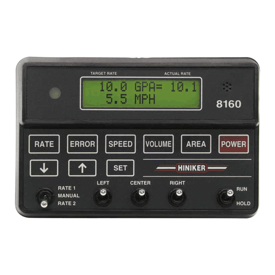
Page 10: Display
8 System Overview DISPLAY The display is used to provide to the user impor- tant information on the operation of the system and its components. TARGET RATE DWG. NO. 5807 The left side of the top line on the display will normally show the Target Application Rate. -
Page 11: Error Messages
-99%. In this condition you are un- der applying by more then 99%. When displayed this reminds the operator that the 8160 is in the Hold Mode and is no longer doing any control. All boom valves are turned off and Area and Volume stop accumulating. -
Page 12: Sim
DWG. NO. 5817 OVER LOW FLOW This is short for overflow. This indicates the 8160 has calculated a number greater than allowed. The LOW FLOW message will flash to warn that Clear Area or Volume back to zero or ignore this the console can no longer operate in the Run message. -
Page 13: System Connections
This is the Flow input. It connects to the other device using RS-232 communications and Flowmeter. the Hiniker Protocol or Generic Protocol for Vari- able Rate Applications. This connector is located BOOM CONNECTOR on the back of the console. This is the connection for the Boom control valves. -
Page 14: 12 Operation
Set-up procedure and the Distance Calibration procedure before attempting to use this console. It is important to insure that the 8160 is control- Failure to do this will result in faulty control and ling your sprayer properly. The RATE and ER- inaccurate Volume, Area, and Speed data. -
Page 15: Variable Rate
To prevent a “LOW FLOW” message as you slow down the 8160 can automatically stop reducing The 8160 will continue to apply at the rate speci- the flow at a preset minimum flow rate. This pre- fied in the last received message until it receives vents a poor spray pattern from your nozzles. -
Page 16: Menu
MENU To enter the Main Menu press and hold the SET key for 2 seconds. The 8160 is constructed to allow for maximum flexibility when changing between Spray and Upon entering the main menu the current select- NH3 applications. The console will be config- ed mode will be displayed, either Spray or NH3. -
Page 17: Selecting Operating Mode
“answer” to the question, then press SET. The new “Value” will be saved and you will advance There are two separate modes for the 8160, the to the next menu item based on your answer. Spray mode, and the NH3 mode. All calibration... - Page 18 16 Operation SPRAY MODE SET-UP Upon entering the main menu the current select- ed mode will be displayed, either Spray or NH3. This section is for Sprayer Set-Up only. Refer to If the NH3 mode is displayed then press the the NH3 Set-Up section for Anhydrous Ammonia key to change the answer to NO then press SET.
-
Page 19: Spray Setup
Operation 17 NH3 MODE SET-UP Upon entering the main menu the current select- ed mode will be displayed, either Spray or NH3. This section is for NH3 Set-Up only. Refer to the If the Spray mode is displayed then press the Spray Set-Up section for Spray applications. - Page 20 18 Operation OPTIONS MENUS The Options menu contains the following options and procedures: There are two “Options” menus. They are iden- tical except that the Minimum Flow Feature is Distance Calibration not available for NH3 applications. The settings Distance Measurement for each of these option menus are stored sepa- Remote Run/Hold Enable rately for each operating mode (Spray or NH3).
-
Page 21: Options Menu
“ON”, “SET”, “ADJ”, or “OFF” then press SET. Refer to the Minimum Flow procedure for instructions. PROTOCOL = Select the “HINIKER” or “GENERIC” protocol using the keys. If selecting HINIKER the “GENERIC” protocol you are prompted to turn “Logging ON or OFF” and enter a “FIELD”... -
Page 22: Speed Sensor Calibration
It is not necessary to perform the Distance Cali- The console will count ALL pulses between the bration when using the HINIKER GPS Speed PRESS TO START and the PRESS TO END key Sensor. Enter 2.00 Pulses/Ft for the Distance presses. -
Page 23: Distance Measurement
Distance Measurement feature. The The Distance Measurement feature will allow you maximum speed while measuring is 10 MPH. to use the 8160 to easily measure a distance. The Area counter does not accumulate while measuring. DISTANCE MEASURMENT PROCEDURE... -
Page 24: Remote Run/Hold
22 Operation REMOTE RUN/HOLD A proximity sensor may be used for the Remote Run/Hold switch. When metal is present in front This option will reduce the number of controls the of the face of the sensor, the console will remove operator must use on end rows and turns. -
Page 25: Minimum Flow
Operation 23 There are two ways to set the minimum flow limit. MINIMUM FLOW “SET” allows you to use the keys to ad- This feature is used to set a limit on how low the just the servo valve to adjust the pressure at the console can reduce the flow during automatic op- nozzles. -
Page 26: Serial Protocol
Available selections are “HINIKER” and “GENERIC”. If “GENERIC” is selected HINIKER then the 8160 will prompt you for “LOGGING ON/OFF” and a “FIELD # “ LOGGING = OFF Selecting “LOGGING = ON” will instruct the 8160 to start sending data to the serial port once per second. -
Page 27: Test Input Routine
When the Question “DISPLAY TARGET RATE UNDER 1%?” is being displayed, use the The 8160 will always try to adjust the Actual Ap- keys to adjust the %, then press SET. The plication Rate to within 1% of the Target Rate. -
Page 28: Installation
26 Installation - Basic Unit INSTALLATION - BASIC UNIT TITLE CONSOLE MOUNTING CABLE CONNECTED TO POWER BATTERY Select a convenient location to mount the con- SERVO SERVO VALVE trol console. SPEED SPEED SENSOR This location should provide the operator with a FLOW FLOWMETER good view of the console display and easy ac-... -
Page 29: 8150 Adapter
Installation - Basic Unit 27 8150 ADAPTER An adapter (Part # 38815014) is available for us- ing an 8160 to replace an 8100 or 8150 console without changing any of the wiring. All cables are the same except the BOOM Cable. To use... -
Page 30: Speed Sensors
28 Installation - Speed Sensors INSTALLATION - SPEED SENSOR TITLE HUB PLATE SPEED SENSOR The hub plate speed sensor may be installed either on the tractor or the implement. Do not install the sensor on a driven wheel. This will cause readings to be incorrect due to wheel slip- page. - Page 31 Installation - Speed Sensors 29 DWG. NO. 123 DWG. NO. 5800 The 8 bolt hub plate is for (8) 5/8 inch bolts on a The 4 bolt hub plate is for (4) 9/16 inch bolts on a 5-inch bolt circle. 8-inch bolt circle.
-
Page 32: Radar Adapters
363-008-003 PART #363-008-003 This standard interface is used to connect a Magnavox/Phillips radar to the 8160 console in a stand-alone mode. In the stand-alone mode the radar is not connected to any other system. DWG. NO. 2750 To install, connect the interface to the radar and mount in a convenient location. - Page 33 On the system. The interface divides the signal, enhances it and routes it to the Hiniker system. Adapter ca- male shells only, clip off the small indexing tab that prevents the mating of a black and gray shell to- bles are available for all radars.
-
Page 34: Gps Speed Sensor
Mount the Hiniker module to allow for direct view- ing of the indicator lights. The supplied Velcro VELCRO MOUNT: may be used for mounting the Hiniker module to the top or sides of your console. - Page 35 Refer to the console’s Operating and Installation Manuals for the proper connector pin-out. OPERATION: There are two indicator lights on the Hiniker module. The green light is the satellite lock in- dicator. It flashes once per second when the module is communicating with the GPS sensor, but the sensor has not yet obtained a position lock on the satellites.
-
Page 36: Sprayer Applications
To determine required gallons per minute with your sprayer, use this formula. This section describes how to plumb a sprayer for use with the Hiniker 8160 controller. GPA x MPH x Width (ft.) GPM = There are two basic configurations. The Inline system and the Bypass system. -
Page 37: Inline System
Installation - Spray Control A filter is recommended before the flowmeter. INLINE SYSTEMS In an Inline System the Flowmeter and Servo Recommended mounting HM860 Control Valve MUST be after all agitation and Flowmeter is vertical with the arrow pointing up. Bypass lines and inline with all the flow to the booms. -
Page 38: Bypass System
Installation - Spray Control BYPASS SYSTEMS If the Servo Valve is mounted in an existing by- pass line or agitation line, be sure to remove any parts that may restrict the flow. For exam- In a Bypass System the Flowmeter measures all the flow to the booms, but the Servo Valve ple, some agitation lines have nozzles inside controls the flow bypassed back to the Tank (or... -
Page 39: Typical Wiring-Sprayer
Installation - Spray Control DWG. NO. 5931... -
Page 40: Flowmeter
38 Installation - Spray Control NOTE: Make sure arrow on the flowmeter is HM860 FLOWMETER pointing in the direction of the flow. The HM860 FLOWMETER has an output sig- nal proportional to the flow through it. There are STEP 4 Connect input hose... -
Page 41: Servo Valve
3-wire is not. A 10 foot cable is provided to go from the hitch to the 8160 console. Be sure to connect the 10 foot There are three valve sizes. The standard servo cable to the receptacle labeled “Servo.” Both ca- bles are labeled “Servo”... -
Page 42: Boom Valve
40 Installation - Spray Control Boom Valve Connections The Weatherpack connectors will plug directly into 1AV-M valves from KZCO. Before making The “Ball Valve” Cable is for connecting to three connections, check the wiring on your particular three-wire ball valves. It has three 3-pin Weath- valve to see if it is wired the same. -
Page 43: Remote Run/Hold
Installation - Spray Control 41 Remote Run/Hold DANGER: USE EXTREME CAUTION WHEN USING THE REMOTE RUN/ The remote Run/Hold is available at the console HOLD FEATURE. ALWAYS SWITCH and at the end of the boom control cable. It con- THE CONSOLE OFF BEFORE LEAVING THE sists of a 2-pin connector. -
Page 44: Anhydrous Ammonia Applications
A proximity sensor may information, and read all safety precautions also be used. found in the “HINIKER ANHYDROUS AMMO- NIA MONITORING AND CONTROL SYSTEM MANUAL” Refer to manual part number 360- 000-246 Revision E or later for heat exchang- er manufactured prior to 2007. -
Page 45: Typical Wiring-Nh3
Installation - Anhydrous Ammonia 43 8160 TYPICAL WIRING - NH3 APPLICATION 8160 CONSOLE TARGET RATE ACTUAL RATE 8160 RATE ERROR SPEED VOLUME AREA POWER 2 CONDUCTOR RUN/HOLD HINIKER 3 CONDUCTOR EXTENSION CABLE LEFT CENTER RIGHT RATE 1 BATTERY CABLE 6' 38816012... -
Page 46: 44 Troubleshooting
The 8160 is easy to troubleshoot if you ap- proach it in an organized manner. There are four The next step is to narrow the problem(s) down primary parts. -
Page 47: Console Symptoms And Possible Causes
Troubleshooting 45 CONSOLE - SYMPTOMS POSSIBLE CAUSE A. Is completely dead. Battery voltage below 6 volts. 1, 2, 3, 4, and 6. Bad cable. B. Displays “Default In Use” each time console Battery connections reversed or not connect- is turned on. ed directly to battery. -
Page 48: Using Test Inputs
46 Troubleshooting USING TEST INPUTS CABLE AND CONNECTOR TROUBLESHOOTING The Test Input routine allows you to Test the NOTE: Splices in cables are not recommended. Flow, Speed, and Run/Hold inputs of the con- If a splice is necessary to eliminate down time, sole. - Page 49 Troubleshooting 47 In general, a continuity check on the cable 7 PIN CONNECTOR is a good check; however, it may not find a intermittent short or open in one of the ca- bles. CONSOLE/CABLE CONNECTORS In the connector there are numbers stamped in the rubber next to each female socket and male pins.
-
Page 50: Speed Sensor
Pin or Cable Cable The speed sensor is a very important component Socket Wire Wire in the 8160 system. If the speed sensor is not func- Numbers Color Color Description tioning properly, it will have an adverse effect on Pink Orange Run/Hold Input. -
Page 51: Hm860 Flowmeter
Troubleshooting 49 HM860 FLOWMETER MAINTENANCE TROUBLESHOOTING For all applications, except anhydrous ammonia, the HM860 FLOWMETER should be thoroughly flushed with clean water immediately after each Make sure direction of flow (arrow on flowmeter) is correct. use. Check flowmeter for debris slowing or stopping Periodic disassembly and cleaning of the HM860 the turbine. - Page 52 50 Troubleshooting INLET BUSHING TURBINE O RING SENSOR OUTLET HOUSING BEARING BUSHING BEARING DECAL CALIBRATION DWG. NO. 2767 DISASSEMBLY NOTE: Damage may result to the sapphire bearing if the screw is inserted too far. Refer to drawing 2767 for proper parts place- ment.
-
Page 53: Flowmeter Calibration Test
Troubleshooting 51 C. NOTE: Each time the flowmeter gener- FLOWMETER CALIBRATION TEST ates a pulse, the 8160 will count up by All flowmeters are factory calibrated and should 1. Therefore, the console is counting the measure GALLONS with at least 98% accuracy. - Page 54 The servo valve does the actual controlling or ad- justing of the flow mate. If the servo valve is not There is no feedback (pin 1) to the 8160 to let it functioning properly the gallons-per-acre readout know if it is full open or full closed.
-
Page 55: Servo Valve
8160 prior to applying voltage directly To check the Motor, first disconnect the valve to the motor may cause permanent failure of the from the 8160, and then apply 10 to 12 volts to 8160 console. the terminals on top of the motor (any polarity). - Page 56 2 or 3 to operate should be replaced. The valve should respond the valve. The 8160 can vary the discontinuity to both the “ ” and “ ” key. If the valve only times to vary the valve speed.
-
Page 57: Remote Run/Hold
These dimensions must be adhered to or the sensor will not work properly. The 8160 has a routine that will help you locate the faulty component. This routine is listed in the OPTIONS menu under Test Inputs. After an- swering yes (Y) to the “Test R/H”... -
Page 58: 56 Appendix
1 start bit, 8 data bits, no parity bit, and 1 stop bit is in spray mode or as pounds per acre of actual for the “Hiniker” protocol and 2 stop bits for the nitrogen if it is in NH3 mode. - Page 59 “HINIKER” Additional Messages XX = Current Active Boom width (inches) Hun- dreds digit While the 8160 can recognize and react to the XX = Current Active Boom width (inches) Tens following messages as described, they are not digit required.
- Page 60 Checksum = 37 24 = Start of message 06 = Read Message The 8160 will transmit a Target Rate Reply mes- 02 = Two Character Message sage in response to a Read Target Rate mes- sage. It will reflect the current target rate 1.
-
Page 61: "Generic" Protocol
XX = Current Active Boom width (inches) Tens 03 = Channel Type Info digit XX = Current Active Boom width (inches) Units Depending on which mode the 8160 is in the re- digit maining characters of the message will be: 00 = NULL... - Page 62 D3, TD, C1, C2, and C3 strings will be sent by the Console. All console output strings begin with $R035J With Data Logging on sending the 8160 an RC C1 Calibration String (C1) message that changes Rate1 to a rate different...
- Page 63 Reference allows user to enter up to a four-digit number to represent a field. rolls over to 0.0 and continues to accumulate. this field will contain the existing area data of the 8160 D2 Data String (D2) The D2 data string contains total volume and field volume information.
-
Page 64: Parts Breakdown
36015005 8160 console only 388-003-003 10 Ft. 3 conductor Speed extension cable 8169 8160 Console, Manual, and 7 to 4-pin boom 388-003-020 20 Ft. 3 conductor Speed extension cable adapter. Replaces Spray Commander, 8100 or 363-003-020 Speed Sensor w/ 20 Ft. 3 conductor cable 8150 console. -
Page 65: Swath Control
If all section valves are off, the Hiniker console If connected as shown below the 8160 will per- will be in Hold. The 8160 will operate as if it were form the application control while the swath con- controlling the boom section valves. -
Page 66: 64 General Information
128 feet in a row of grain sor- ghum, for instance, can reduce yields by 5%. To help increase your application efficiency and assure maximum results, the Hiniker Company has published the following guidelines and spe- cial instructions. -
Page 67: Nozzle Spacing
General Information 65 NOZZLE SPACING AFFECTS G.P.A. TRACTOR SPEED AFFECTS G.P.A. 20 GPA nozzles spaced 20 inches apart will ap- If you are using 30 Gallon, Per Acre Tips and ply 20 gallons per acre. Spaced 40 inches apart, traveling 4 miles per hour, you are applying 30 10 gallons per acre. -
Page 68: Boom Height
66 General Information HOLLOW CONE nozzle pattern is also SPRAY ANGLE slightly overlapped for uniform coverage. Misalignment is impossible. Used for broad- The spray angle of the nozzle determines the casting of herbicides or insecticides. Gives boom height. Flooding nozzles have a wide excellent plant coverage with drops. -
Page 69: Nozzle Selection
General Information 67 THEORETICAL COVERAGE AT VARIOUS DISTANCES (IN INCHES) FROM NOZZLE ORIFICE Included Spray 2” 4” 6” 8” 10” 12” 15” 18” 24” 30” 36” 48” Angle 5° 0.2” 0.4” 0.5” 0.7” 0.9” 1.1” 1.3” 1.6” 2.1” 2.6” 3.1” 4.2”... - Page 70 68 General Information All nozzle tables or charts will give you gallons per spacing and ground speed the required pressure minute (GPM) for several pressures. Using the to apply a desired Gallons Per Acre can be found correct table for the type of nozzle (flat, flood, etc.) by solving: that you selected, find the GPM closest to the de- Where:...
-
Page 71: Band Spraying
1.44 To recalculate the total ACRES, as might be the 14.0 Ibs. per gallon 1.68 case if you used the 8160 for Band spraying and 16.0 Ibs. per gallon 1.92 would like to know the total acres of the whole field, use the ratio procedure shown below. -
Page 72: Before You Go To The Field
An electronic monitor such as the 8160 will make this task very easy. An established routing of proper mainte- nance will soon pay for itself. -
Page 73: Glossary
Glossary 8150 Adapter 7-pin to 4-pin adapter cable that allows the 8160 to be used with 8150 boom wiring This key is used to; 1) increase 2) scroll up and 3) answer “Yes” . This key is used to; 1) decrease 2) scroll down and 3) answer “No”... -
Page 74: Default Values
Variable Rate The ability to change Application Rates on the go based on an application map. Variable Rate Message An application rate received from the serial port. It must conform to one of the Hiniker protocols. Ver X.XX Software Version Number displayed during power up. - Page 75 The only warranty Hiniker Company (Hiniker) gives and the only warranty the dealer is authorized to give is as follows: We warranty new products sold by Hiniker or authorized Hiniker dealers to be in accordance with our published specifications or those specifications agreed to by us in writing at time of sale. Our obliga-...
Need help?
Do you have a question about the 8160 and is the answer not in the manual?
Questions and answers