Table of Contents
Advertisement
Advertisement
Table of Contents

Summary of Contents for Ezy-Lift Ezy 2000
-
Page 2: Table Of Contents
Read and obey all Danger, Warning, Caution, and Operating Instructions on the Ezy-Lift and in this manual. Make sure that all placards are in place and legible. Failure to comply with safety precautions in this manual and on the Ezy-Lift is a safety violation that may result in serious injury, death, or property damage. -
Page 3: Product Specifications
PRODUCT SPECIFICATIONS Lifting Capacity 2000 Pounds for 8 foot cargo beds Power Supply 12 VDC operation from vehicle battery, 150 AMP fuse at vehicle battery Hydraulic System Bi-Directional hydraulic pump & flow control valve, two 3” hydraulic cylinders pro- vide lift rotation of the boom arms Winch Designed for lifting with 159:1 gear rotation, full load mechanical brake, 5:1 safety factor... -
Page 5: Installation
1/4 Flat Washer Anchor Points (Chevrolet Only) Extra Parts The Ezy-Lift is shipped with a few extra attaching parts i.e. screws, washers, nuts, and bolts to ensure that there is enough to complete the installation. Having leftover attaching parts is normal. - Page 6 Read the instructions completely before installation. It is recommended not to skip steps. We have carefully considered the order of each step to ensure the best possible installation with the fewest possible problems. Prior to installation, park the truck on a level surface, set the parking brake and chock the wheels for safety.
- Page 7 BEGINNING STEPS LEAVE EZYLIFT FRAMES SECURED TO PALLET Remove the tailgate and remove the tail light assemblies. (Do not remove tail lights for Chevrolet Installs) If installing the unit in a Chevrolet Pick Up truck turn to pages 8 through 13 for Arm Frame installation instructions.
- Page 8 Note the illustration to the left. The large pre- drilled holes are used to attach the frame to the wheel well with 5/16” screws at a later stage in the installation. The small holes are used, along with the self tapping screws, to attach the “L” Spacer to the unit frame before installation.
-
Page 9: Chevrolet Unit Frame Installation
The following section (pages 8 through 13) provide Boom Arm Frames installation instructions for Chevrolet trucks only If the Ezy-Lift is being installed in a Ford, Toyota or Dodge truck please turn to page 14 to continue Boom Arm Frames installation instructions. - Page 10 Chevrolet Frame Installation The installation of the unit Arm Frames in a Chevrolet pick up truck differs from that of other pick up trucks. After the frames are installed the remainder of the installation is the same for other truck makes and models. The next seven pages address Chevrolet Arm Frame installations only.
- Page 11 BEGINNING STEPS LEAVE EZYLIFT SECURED TO PALLET Remove the tailgate before installation. Set the Bed Mounting Shims in the bed grooves nearest the wheel wells. See illustrations below for position- ing. Set the Bed Mounting Shims in the grooves nearest the pick up truck wheel wells. There is no need to se- cure the shims at this stage.
- Page 12 Mount the Side Fillers Unlike the Side Fillers which are used to fill gaps between the unit Arm Frames and bed side walls on every other truck, the Chevrolet Side Filler is one of four mounting brackets for the unit Arm Frame.
- Page 13 Take the unit frame that has the hydraulic pump and place it on the drivers side of the pick up truck bed with the arm end point- ing forward toward the truck cab. Take the remaining unit frame and place it on the truck bed on the passenger side. Be careful not to set the unit on the hydraulic pump hoses.
- Page 14 MOUNT THE FRAME TO THE WHEEL WELLS Now that the unit Arm Frames are secured to the Side Filler brackets undertake the following steps to attach the frames to the truck wheel wells. Count back one from the truck cab end or front end. The second hole is the first hole to drill through.
- Page 15 Use the disposable 90° Square and square up the unit Arm Frame with the bottom of the truck bed. Once the frame is square with the bed be- gin to tighten the 1/4” screws that secure the frame to the Side Filler Brackets. Tighten these completely the length of the frame.
-
Page 16: Frame Installation-All Non Chevrolet Trucks
Boom Arm Frames Installation Ford, Dodge & Toyota Section This section applies to the Boom Arm Frame installation on Ford, Dodge and Toyota trucks only. After finishing these steps proceed with the installation covered in the sec- tions for hydraulic and electrical installation. - Page 17 Dodge, Toyota and Ford truck Boom Arm Frame Installations Take the unit frame that has the hydraulic pump and place it on the drivers side of the pick up truck bed with the arm end pointing forward toward the truck cab. Take the remaining unit frame and place it on the truck bed on the passenger side.
- Page 18 MOUNT THE FRAME TO THE WHEEL WELLS Now that the unit Arm Frames are secured to the Side Filler brackets undertake the following steps to attach the frames to the truck wheel wells. Count back one from the truck cab end or front end. The second hole is the first hole to drill through.
- Page 19 Set the Rear and Front Foot Brackets Align the 5/16” drill bit through the holes in the brackets and drill through the truck bed for both the front and rear Foot Brackets. Run the screws through the holes and put the washers and nuts on from the under side but only hand tighten.
- Page 20 How to use the RNHT Rivet Nut Hand tool The RNHT hand tool comprises 3 parts, the upper body (figure A), the lower body (figure B) and the socket head cap screw (figure C). Put the socket head cap screw through the tool in the orientation shown in figure C. Thread the rivet nut on to the screw until it rests against the underside of the bottom.
-
Page 21: Install Hydraulic & Power-All Truck Units
HYDRAULIC HOSES & POWER CORDS Feed and attach hydraulic hoses On the driver’s side (pump side) drill three 1” holes through the bottom of the truck bed using a hole-saw. Insert a rubber grommet in each hole. (Note Make sure to check under the truck for an open area before drilling.) On the passenger side drill two 1”... - Page 22 Use a 9/16 and 5/8 open end wrench to secure the hose ends to the fittings on the pump. Each of the two fittings are different, one male and one female. It is not possible to hook them up incorrectly. After the hoses are securely connected to the pump pull the slack back through the feed holes towards the passenger side frame.
- Page 23 Connecting the Electrical Cords Open the red Power Cord package. Locate the long red Power Cord and lay it out the length of the truck along side the driver’s side. Find the Fuse Box and Fuse and the short Power Cord. Position the short cord from the battery to a clear area of the truck’s engine compartment firewall.
- Page 24 Check the Remote Control and the Hydraulic Fluid in the Lift Pump Plug the female fitting into the receptacle on the rear of the pump side frame. Depress and Both of the unit arms will begin to move up and back towards the rear of the truck bed.
- Page 25 As the arms come out, the hydraulic fluid level in the pump reser- voir will drop towards the bottom indentation in the reservoir (indicated by the red line in the illustration). Allowing the fluid level to drop below the bottom indentation may lead to air enter- ing the system.
- Page 26 Locate the Winch Power Cable in the pump side arm and pull the ends out of the arm. Connect the power cable to the fish lead and pull the fish lead through the Winch Power Cable Feed Hole. Set the electrical leads aside. Loosely secure the crossbar to the unit arm brackets with the 5/16”...
- Page 27 It will probably be necessary to tap in the cross bar end caps with the rubber mallet. Securely tighten the six bolts securing the crossbar to the arms. Finish Frame Construction Place the Frame Side Filler (Except Chevrolet) in between the Boom Arm and the bed side wall. Se- cure to the Frame with the 1/4 inch screws.
-
Page 28: Know Your Ezy-Lift
Ezy-Lift system. WARNING Because Ezylift, Inc. has no direct involvement or control over the Ezy-Lift operation and ap- plication, conforming to good safety practices is the responsibility of the owner, the user, and its operating personnel. - Page 29 Never use the unit for lifting, supporting or transporting people! Never stand beneath the load or Ezy-Lift frame or use over areas where people Do not work under the load unless the load is supported by blocks, jacks or solid footing that will support a weight greater than the weight of the entire load.
-
Page 30: Operation
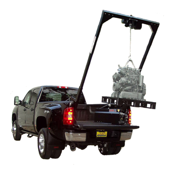
NEVER MOVE A TRUCK WITH A SUSPENDED LOAD. OPERATION Your Ezy-Lift system operates from the vehicle’s 12 volt battery which provides power to the crane winch and the hydraulic power unit. The hydraulic unit is completely self-contained with a DC motor, gear pump, reservoir, load hold checks and relief valves to prevent over-loading. - Page 31 Become comfortable with operating the system. Practice moving the boom in and out and unspooling and spooling the winch cable. With the winch cable become familiar with re-spooling the wire rope with the tension necessary to rewind evenly without the wire overlapping.
-
Page 32: Inspection & Maintenance
Ezy-Lift Inspection & Maintenance Ezy-Lift is designed to give years of carefree operation. However, as with any mechanical product, periodic inspection and maintenance is require keep the unit in optimal operating con- dition. - Page 33 When replacing the wire rope be sure to insert the attaching end of the wire rope into the correct end of the drum hole (See Figure 2). Tighten the set screw securely. To insure the correct wire rope replacement part, obtain the part from Ezy-Lift. Use heavy leather gloves when handling the wire rope.
-
Page 34: Trouble Shooting
MAINTENANCE Your Ezy-Lift lifting system should b serviced every 2 years or 400 hours of normal opera- tion. That maintenance includes: Inspect and lubricate bearings Check all hydraulic fittings for leaks or signs of wear, tighten or replace as necessary. -
Page 35: Warranty
WARRANTY Ezy-Lift, Inc. warrants the Ezy-Lift product to the original Buyer against defec- tive materials and parts for one (1) year from the date of purchase Ezy-Lift’s sole and exclusive liability, and the Buyer’s sole and exclusive remedy, under this warranty, is the repair or replacement of any materials or parts determined to be defective. -
Page 36: Hydraulic Diagram
HYDRUALIC DIAGRAM...
Need help?
Do you have a question about the Ezy 2000 and is the answer not in the manual?
Questions and answers
Looking for A cylinode for a ezy lift serial # 101200197 model# 2000L