Table of Contents
Advertisement
H6HK Series Electric Heater Kit
INSTALLATION INSTRUCTIONS
Installation in Standard & Variable Speed Indoor Air Handlers
These instructions are primarily intended to assist qualified individuals experienced in the proper
installation of heating and/or air conditioning appliances. Some local codes require licensed
installation/service personnel for this type equipment. All installations must be in accordance
with these instructions and with all applicable national and local codes and standards.
Read these instructions thoroughly before starting the installation. Follow all precautions and
warnings contained within these instructions and on the unit. The instructions included with
this keater kit are for installations in air handlers only.
IMPORTANT
DO NOT DESTROY. PLEASE READ CAREFULLY &
KEEP IN A SAFE PLACE FOR FUTURE REFERENCE.
Advertisement
Table of Contents

Summary of Contents for Nordyne H6HK Series
- Page 1 H6HK Series Electric Heater Kit INSTALLATION INSTRUCTIONS Installation in Standard & Variable Speed Indoor Air Handlers IMPORTANT These instructions are primarily intended to assist qualified individuals experienced in the proper installation of heating and/or air conditioning appliances. Some local codes require licensed installation/service personnel for this type equipment.
-
Page 2: Table Of Contents
GENERAL INFORMATION Variable Speed Air Handlers ........7 About the heater kit H6HK Series electric heater kit is approved for field WIRING DIAGRAMS ............8 installation in B5, B6, MB7, HMG, HMB, & HCG, air Figure 7 - Single Ph. - 5Kw Series ......8 handlers. -
Page 3: Clearances To Combustibles
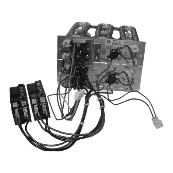
Tables 2 - 4 (page 7) for all Heater Kit applications. supply circuit. Electric heater kits greater than 10 • These instructions are written assuming the air kw are supplied from the factory configured for use handler is in the upflow position (outlet facing up). with two supply circuits. - Page 4 7 - Pin Connector 2 - Pin Connector Circuit Breaker Bracket Figure 2. Sample Installation (shown with access door removed) Standard Air Handler (A & B Size) Variable Speed & Standard Air Handler (C Size) Minimum Circuit Max. Over-Current Minimum Circuit Max.
-
Page 5: Electric Heater Kits With Circuit Breakers
For 25 kw & 30 kw Heater Kits: Attach the 4-Pin and 3-Pin Harnesses to the Auxiliary circuit board. NOTE: A wiring diagram and a rating label are supplied with the electric heater kit. Affix the wiring diagram to the blower housing. -
Page 6: Power Wiring
Power Wiring All wiring must comply with the current revision of the National Electric Code and must be sized for the minimum ampacities as listed on the unit data label or in Table 1. Refer to the detailed wiring diagrams (pages 8 - 14) for proper connections. -
Page 7: Variable Speed Air Handlers
Standard 3 Speed Motors Minimum Required Blower Cabinet Size Terminal 4 = Hi speed Heating Speed Model Terminal 5 = Med speed H6HK- UpFlow Horizontal Downflow Terminal 6 = Low speed 005H Standard C-Cabinets 008H Terminal M1 = Low speed 010H Terminal M2 = Medium Low speed 015H... -
Page 8: Wiring Diagrams
BLACK ELEMENT LIMIT RELAY BLACK POWER NOTES TERMINAL BLOCK 1) If any of the original wire supplied with this unit (for select must be replaced, it must be replaced with wiring models only) material of the same gauge size and temperature rating. - Page 9 BLACK LIMIT ELEMENT RELAY BLACK ELEMENT RELAY BLACK ELEMENT LIMIT RELAY NOTES CIRCUIT BREAKERS 1) If any of the original wire supplied with this unit must be replaced, it must be replaced with wiring material of the same gauge size and tempera- GROUND SUPPLY VOLTAGE ture rating.
- Page 10 Figure 11. Wiring Diagram for H6HK Single Stage Air Handler with Circuit Breaker(s) - 24 kw Series...
- Page 11 Figure 12. Wiring Diagram for H6HK Single Stage Air Handler with Circuit Breaker(s) - 25 kw Series...
- Page 12 Figure 13. Wiring Diagram for H6HK Single Stage Air Handler with Circuit Breaker(s) - 29 kw Series...
- Page 13 Figure 14. Wiring Diagram for H6HK Single Stage Air Handler with Circuit Breaker(s) - 30 kw Series...
- Page 14 GRAM Legend Field Wiring NOTES Factory Wiring: Low Voltage 1) The blower motor speed tap connection may not be as shown. See the Installation Instructions. High Voltage 2) Disconnect all power before servicing. 3) Transformer may have a dual voltage primary tap. Match the tap position with the supply voltage used. 4) If the Internal wiring is replaced, use only 105 °...
- Page 16 INSTALLER: PLEASE LEAVE THESE INSTALLATION INSTRUCTIONS WITH THE HOMEOWNER Specifications & illustrations subject to change 709524A (Replaces 7095240) without notice or incurring obligations. (01/14)
Need help?
Do you have a question about the H6HK Series and is the answer not in the manual?
Questions and answers