
Summary of Contents for Athena GTX WVSM 5.0
- Page 1 WVSM wireless vital signs monitor Non-Invasive Blood Pressure | Pulse Oximetry | Electrocardiogram Service Manual WVSM 5.0 Service Manual 1 of 60 ®...
- Page 2 CAUTION: Federal law (USA) restricts this device to sale by or on the order of a licensed healthcare professional. Athena GTX® reserves the right to make changes and improvements to this manual and the products it describes at any time, without notice or obligation.
-
Page 3: Table Of Contents
Table of Contents 1.0 Safety Information - General .................... 7 1.1 Contraindications ......................7 Warning ........................... 8 1.3 Cautions ......................... 11 2.0 Introduction ........................13 2.1 Intended Use ........................13 Manual Overview ......................13 3.0 Device Overview ......................14 3.1 Controls, Indicators and Symbols ................... 14 3.1.1 Front Panel ........................14 3.1.2 Bottom Panel ....................... - Page 4 5.4 WVSM® Default Alarm Limits ..................42 5.4.1 Using a PC ........................42 5.4.2 Using the WVSM iOS app .................... 44 5.5 PC Default Alarm Limits for Manual Parameter Data .............45 6.0 Maintenance ........................47 Cleaning ......................... 47 6.1.1 WVSM® Device ......................47 6.1.2 Pulse-Ox Sensor ......................47 6.1.3 ECG Cables ........................47 6.1.4 NIBP Cuffs ........................48 6.1.5 Power Adapter and Data Cable ................... 48 6.2 Recharging the Battery ....................
- Page 5 Table of Figures Figure 1. WVSM® Front Panel ....................14 Figure 2. WVSM® Bottom Panel ....................16 Figure 3. WVSM® Top Panel ..................... 17 Figure 4. Select Internet Protocol ....................27 Figure 5. Properties Dialog Box....................28 Figure 6. IP Address Properties ....................29 Figure 7.
- Page 6 Table of Tables Table 1. Front Panel Functions ....................15 Table 2. Bottom Panel Sensor Connections ................16 Table 3. Top Panel Connections ....................17 Table 4. Symbols Table Labels ....................18 Table 5. Symbols Table Device User Interface ................19 Table 6.
-
Page 7: Safety Information - General
1.0 Safety Information - General WARNING: Before servicing the WVSM® device, read and understand this manual in its entirety. WARNING: The equipment is provided with signal terminals supplied by and to be connected to secondary circuits complying with Class 2 requirements. WARNING: Be careful not to position the WVSM®... -
Page 8: Warning
WARNING: To avoid risk of electric shock, this equipment must only be connected to a supply mains with protective earth/grounding. WARNING: Use only Athena GTX approved accessories with the WVSM® device. Improper functioning and/ or insufficient protection during defibrillation could result if alternate ECG leads are used. - Page 9 WARNING: The use of accessories and cables other than those specified by Athena GTX may result in increased electromagnetic emissions and/or decreased immunity of the WVSM® device. See Accessories list later in this manual.
- Page 10 WARNING: Be sure that all blood pressure tubing is not pinched and that flow is not restricted in any way while taking blood pressure measurements. The cuff must be correctly fitted, placed, and checked to be operational. The Patient Sensor Connections section below has guidelines for proper fitting. If the cuff is not fitted properly, or the tubing is pinched the WVSM®’s accuracy can be diminished or can fail.
-
Page 11: Cautions
WARNING: There are no serviceable items in the WVSM® device. Do not attempt to disassemble. For repairs or battery replacement, contact Athena GTX. WARNING: A multiple socket outlet or extension cord may not be connected to the WVSM® device. RISKS of connecting the WVSM®... - Page 12 CAUTION: The Pulse-Ox function complies with IEC EN 60601-1-2:2001 for electromagnetic compatibility for medical electrical equipment and/or systems. This standard attempts to reduce the occurrence of an electrical device interfering with typical medical installations. CAUTION: Portable or mobile RF communications equipment may affect the function of the WVSM® device. CAUTION: Readings may be affected by the use of an electrosurgical unit (ESU).
-
Page 13: Introduction
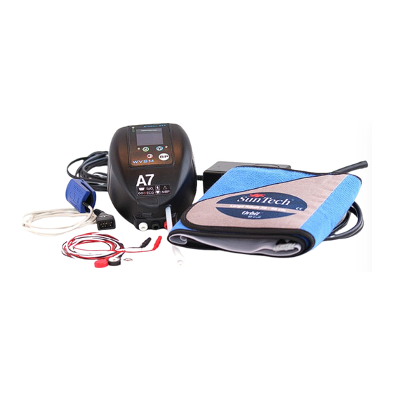
2.0 Introduction 2.1 Intended Use The Wireless Vital Signs Monitor (WVSM®) is intended to be used as an adult patient monitor. It is indicated as a single or multi-parameter vital signs monitor for ECG, noninvasive blood pressure (NIBP) and SpO . -
Page 14: Device Overview
, noninvasive blood pressure and heart rate). WVSM® can be used as a standalone device, with a Personal Digital Assistant (PDA) or Personal Computer (PC). 3.1 Controls, Indicators and Symbols 3.1.1 Front Panel WVSM® Front Panel Figure 1. WVSM™ Front Panel Athena GTX SPO2: (mmHg) 120 / 80 AUTO WVSM 1. -
Page 15: Table 1. Front Panel Functions
Table 1. Front Panel Functions Symbol Description Function Green = Battery charging completed Charge Status Indicator Red = Battery charging Off = Charge fault condition Press and hold turns unit on. Press and hold again turns unit off. Power On/Off Button and Indicator Green = Power On Off = Power Off Single tap turns Low Power Mode on Low Power Mode On/Off Single tap again turns Low Power Mode off Alarm Silence Silences audio alarms Press and release Starts/Stops BP. Take BP/BP Mode Selector Press and hold toggles between Normal and Turbo Modes. Press and release toggles between WiFi. On and Off WiFi On/Off Button and Indicator Blue = WiFi On Off = WiFi Off WVSM 5.0 Service Manual 15 of 60 ®... -
Page 16: Bottom Panel
3.1.2 Bottom Panel Figure 2. WVSM® Bottom Panel 1. Pulse-Ox Sensor Connection 2. ECG Cable Connections 3. NIBP Connection Table 2. Bottom Panel Sensor Connections Parameter Sensor/Connector Symbol Defibrillator-Proof Compatible with Nonin Pulse-Ox sensors only. See list Pulse-Ox of recommended accessories in this manual. Compatible with 1.5mm safety plug connectors. Use ECG cables provided with the device. Compatible with SunTech NIBP cuffs. See list of NIBP NIBP recommended accessories in this manual. WVSM 5.0 Service Manual 16 of 60 ®... -
Page 17: Top Panel
3.1.3 Top Panel Figure 3. WVSM® Top Panel 1. AUX Sensor Connection (Future Use) 2. Data Cable Connection 3. AC Adapter/DC Input Port Table 3. Top Panel Connections Port Sensor/Connector Type Power Compatible with 2.5mm 3 contact plug. For future use sensor input only. 3.3V, 6mA Compatible with 2.5mm 4 contact plug. For use with DATA Athena GTX supplied data cable. 3.3V, 6mA Compatible with Athena GTX medical grade AC DC Input adapter. See list of recommended accessories in this 9V, 3A... -
Page 18: Symbols
3.1.4 Symbols Table 4. Symbols Table Labels Symbol/Icon Description Function This symbol advises the reader to consult the Caution, consult accompanying accompanying documents for important safety-related documents information such as warnings and precautions that cannot, for a variety of reasons, be presented on the device itself. This symbol advises the reader to consult the operating Consult instructions for use instructions for information needed for the proper use of the device. Catalog number Device Part Number. Format: XXX-XXXX-XX. Serial number Device Serial Number. Format: XXXX. This symbol is accompanied by the date that the device was Date of manufacture manufactured. Format: MM-YYYY. IPX2 Shows the device is protected to a water ingress level of Water Ingress Rating dripping water at an angle of 15°. Non-ionizing electromagnetic Device includes an RF Transmitter (WiFi 802.11b/g). radiation DC Voltage Indicates where DC voltage is used. Rx Only Requires a prescription for use Must be prescribed by a medical professional. When disposing of or recycling WVSM® or the battery Do Not dispose of in the Trash pack, follow local government ordinances and recycling... -
Page 19: Table 5. Symbols Table Device User Interface
Table 5. Symbols Table Device User Interface Symbol Description Function Green = Battery charging completed Charge Status Indicator Red = Battery charging Off = Charge fault condition Press and hold turns unit on. Press and hold again turns unit off. Power On/Off Button and Indicator Green = Power On Off = Power Off Single tap turns Low Power Mode on Low Power Mode On/Off Single tap again turns Low Power Mode off Alarm Silence Silences audio alarms. Press and release Starts/Stops BP. Take BP/BP Mode Selector Press and hold toggles between Normal and Turbo Modes. Press and release toggles between WiFi. On and Off WiFi On/Off Button and Indicator Blue = WiFi On Off = WiFi Off Battery Fuel Gauge Bars show level of charge. Alarms Enable Audio alarms are active. Alarms Silenced Audio alarms are silenced for 2 minutes. -
Page 20: Table 6. Symbols Table Parameters
Table 5. Symbols Table Device User Interface Cuff is in the process of inflating and BP–In Progress measuring NIBP. Device is Low Power mode to Low Power Mode conserve Battery Table 6. Symbols Table Parameters Symbol Description Function ECG Connection Connector identification and location for the ECG cables. Connector identification and location for the Nonin Pulse- Pulse Oximeter Connection Oximeter sensor. Non - Invasive Blood Pressure Connector identification and location for the SunTech NIBP NIBP Connection Cuff. Type BF applied part Identifies applied part as Type BF. Defibrillation-proof type CF Identifies applied part as Type CF. applied part Table 7. Symbols Table Handheld Device Icons Table 7a. - Page 21 Table 7b. Symbols Table iOS Icons Symbol/Icon Description Function On (Blue): Shows that the Wi-Fi is connected to WiFi Connection a network. On (Blue) Off(Gray): Shows that the Wi-Fi is not connected Off (Gray) to a network. On (Blue): Shows that the Cellular radio is Internet Connection connected to the internet. On (Blue) Off(Gray): Shows that the Cellular radio is not Off (Gray) connected to the internet. Shows the number of patients currently List View connected in List View Number of “Green” Patients Sort patient list with “Green” patients on the top Sort patient list with “Yellow” patients on the Number of “Yellow” Patients Number of “Red” Patients Sort patient list with “Red” patients on the top Menu Settings and Options menu for mobile device Goes to the Home Screen on the mobile device Home and sends the WVSM® Apps to the background (Physical Button on iOS device) (pauses App) Back Active (black) Back to previous screen/view Inactive (light-gray)
- Page 22 Table 7b. Symbols Table iOS ICONS Manual Input Parameters Enters the manual input parameter menu Initiates the find command for the selected Find Command WVSM® device Opens the manual input screen for Glasgow Coma Score Opens the manual input screen for Temp Temperature Opens the manual input screen for Resp Respiration Opens the WVSM® device configuration Configuration screen Opens the WVSM® device specific alarm Alarms limits adjustment screen Used to increase the value selected by one Increase Value unit Used to decrease the value selected by Decrease Value one unit This allows for the ECG waveform “0” baseline to be adjust in the available display window. Choices are 20%, 50% and Baseline Adjust 80% of full scale. An arrow on the left side of the waveform display shows the current baseline setting Returns to the previous screen without Cancel / Exit Menu sending the command or saving any input data...
-
Page 23: Table 8. Symbols Table Pc Icons
Table 8. Symbols Table PC Icons Symbol/Icon Function Description Allows for adjustment of certain settings Opens Settings and Options Menu such as, Graphing Control, and EtCO2 Dongle Control. Allows the adjustment of vital signs Print Settings and Options printing as well as the time interval in which they are to be printed. Single View Allows user to toggle the display from single view to list view, and vice versa. List View Selects amount of time for display to 15 30 remain in Peek Mode (briefly viewing another patient) before reverting back to Peek Time Limit the patient assigned to the main display. Time values are in seconds Opens configuration menu that allows for WVSM® Configuration Settings adjustment of multiple settings including alarms, gain, and BP reading intervals. Used to aid in locating selected WVSM/ patient. Locate Icon Causes selected WVSM®’s display to flash, as well as emit an audible alarm sound. Green “BP” button causes selected WVSM to begin a new blood pressure reading. -
Page 24: General
3.2.4 Outputs The WVSM® has one Data output port that is activated when WiFi is turned OFF. The Athena GTX® data cable provided with the device is required to use this output port. It is a serial interface to the WVSM®. -
Page 25: Pacemaker Rejection Capability
3.2.6 Pacemaker Rejection Capability Title Specification Indicates 30 to 40 bpm for pacemaker pulses AAMI HR Response to “Ineffectively Paced with amplitudes from +2mV to +9mV, -2mV QRS Pattern” to -7mV and pulse widths from 0.1ms to 2ms, with and without overshoot. Overshoot (ANSI/AAMI:EC 13:2002, Sec 5.1.4 f), g), h)) Method A. -
Page 26: Set Up
4.1 Install the WVSM® PC Software Athena GTX recommends closing all programs before installing the WVSM PC Software on a computer. Applications that run in the background, such as virus scanning utilities should be disabled during installation. Before installing the WVSM® PC Software, uninstall any earlier versions that may be on the computer. -
Page 27: Figure 4. Select Internet Protocol
Note: The WVSM® Software Management Suite is capable of connecting to and monitoring a maximum of 20 WVSM® devices. Note: Windows 7 specific instructions can be found on the WVSM Installation CD. Perform the following steps to establish wireless communications. Turn the WVSM®... -
Page 28: Figure 5. Properties Dialog Box
Figure 5. Properties Dialog Box The Internet Protocol (TCP/IP) Properties dialog box will appear. Select Use the following IP address button and enter a unique IP address for the computer. WVSM 5.0 Service Manual 28 of 60 ®... -
Page 29: Figure 6. Ip Address Properties
Figure 6. IP Address Properties Using the suggested setup, the IP address range of 10.19.1.(1-254) has been reserved for PCs running the WVSM®Software Management Suite. When assigning the IP address for the computer, the Responsible Organization should verify that other devices in the area are not utilizing the same IP address. Note: If an IP address conflict occurs (i.e., two or more devices using the same IP address), the network may become unstable and cause communication problems or errors with WVSM®... -
Page 30: Figure 7. Wvsm Network Properties
Figure 7. wvsm Network Properties Check the box Connect even if this network is not broadcasting. WVSM 5.0 Service Manual 30 of 60 ®... -
Page 31: Figure 8. Wvsm Connection Setting
Next select the Connection tab, and check the box Connect when this network is in range. Figure 8. wvsm Connection Setting WVSM 5.0 Service Manual 31 of 60 ®... -
Page 32: Overview Of The Wvsm® Wireless Network - Ad Hoc Mode
Next, under the Wireless Networks tab select Advanced and select Computer-to-computer (ad hoc) networks only. Confirm the setting and press Close. Figure 9. Advanced Network Settings A wireless connection should now be established with the WVSM® device(s), and the system is ready for use. Start the WVSM®... -
Page 33: Default Network Settings
4.4 Default Network Settings WVSM® Devices Each WVSM device comes with a unique IP address in the range of 10.19.(2-254).(1-254). This unique address is included with the documentation provided with each device. The user can change the IP address of the WVSM through a separate utility (Lantronix Device Installer), available on the installation CD. -
Page 34: Considerations When Making Network Changes To The Wvsm® System
Resetting the WVSM® Device IP Address The IP address for the WVSM® device can be reset to a default address of 10.19.254.254 as follows: 1. With the device turned off and the charging cable connected, press and hold the ON/OFF and BP buttons simultaneously. -
Page 35: Install The Ios Wvsm® Mobile App Software
192.168.0.0 to192.168.255.255 (65,636 possible unique IP addresses) 4.6 Install the iOS WVSM® Mobile App Software Athena GTX recommends closing all programs before installing the WVSM Mobile Apps Software on a Mobile Platform. To load the software on an iOS device, perform the following steps: 1. -
Page 36: Responsible Organization Default Configurations And Alarm Presets
5.0 Responsible Organization Default Configurations and Alarm Presets The Responsible Organization (RO) is able to modify the default Preset Configuration and Alarm Limits that are used upon power on and selecting new file on the WVSM® device. The initial User Name and Password have been set at the factory and are as follows: User Name: admin... -
Page 37: Modifying User
5.1.3 Modifying User To modify a user in the RO assigned username and password, perform the following steps: 1. Open the Setting and Options dialog from the menu toolbar 2. Select the Modify option from the Username control 3. Enter in an existing Username and Password in the corresponding input fields 4. - Page 38 Settings and Options About Settings and Options Graphing Control Username Control Delete Modify Graphing Lines (ON) Username Sweep Time (5 second) Password Set Full Height (50 mm) Con rm Admin Username: Graphing Control Admin Password: RS232 Status: Not Connected Attempt RS232 Connect: Status: Apply Connect...
-
Page 39: User Management - Ios App
5.2 RO User Management – iOS app 5.2.1 Adding User To add a user to the iOS device, perform the following steps: 1. Press the Menu Button 2. Select “Users” 3. Enter an existing RO username and password 4. Under “Add New User” enter an unused User Name and Password 5. -
Page 40: Wvsm® Default Configuration Settings
5.3 WVSM® Default Configuration Settings 5.3.1 Using a PC To set the default configuration presets perform the following steps: 1. Open the WVSM® Configuration Settings Icon 2. Log in by entering the RO assigned username and password and pressing Login 3. -
Page 41: Using The Wvsm Ios App
5.3.2 Using the WVSM iOS app To set the default configuration presets, perform the following steps 1. In single patient view, press the WVSM icon 2. Select “Configuration” 3. Change to desired configuration and change the slide switch of “Set as Defaults” to “On” 4. -
Page 42: Wvsm® Default Alarm Limits
5.4 WVSM® Default Alarm Limits 5.4.1 Using a PC To set the default alarm limit presets on the WVSM® perform the following steps: 1. Open the WVSM® Configuration Settings Icon 2. Select NIBP Alarms Tab or Vital Alarms Tab 3. Log in by entering the RO assigned username and password and pressing Login 4. - Page 43 Con guration Settings Con guration NIBP Alarms Vital Alarms SBP Low Yellow: SBP Low Red: SBP High Yellow: SBP High Red: DBP Low Yellow: DBP Low Red: DBP High Yellow: DBP High Red: Save as Startup Defaults Authorization Apply Exit Username: Password: Factory...
-
Page 44: Using The Wvsm Ios App
5.4.2 Using the WVSM iOS app To set the default alarm limit presets on the WVSM® perform the following steps: 1. In single patient view, press the WVSM icon 2. Select “Alarms” 3. Change to desired Default alarm values and change the slide switch of “Set as Defaults” to “On” 4. -
Page 45: Pc Default Alarm Limits For Manual Parameter Data
5.5 PC Default Alarm Limits for Manual Parameter Data To set the default alarm limit presets on the PC for the manually entered parameters, perform the following steps: 1. Double click on the Bell icon next to the parameter 2. Log in by entering the RO assigned username and password and pressing Login 3. - Page 46 Respiratory Rate Alarm Control Alarm Control <= YELLOW <= YELLOW >= >= Save as Defaults Restore Temperature Alarm Control Authorization Alarm Control Username: Login <= 96.0 Password: YELLOW <= 97.1 Status: Not Logged In YELLOW >= 100.8 Cancel >= 103.0 Figure 14d: PC-Touch Respiratory Rate Save as Defaults Restore...
-
Page 47: Maintenance
WARNING: Make sure that the AC adapter is unplugged from the AC power source before cleaning. CAUTION: Use only approved cleaning solutions. See Athena GTX recommended cleaning solutions below. CAUTION: Inspect the WVSM® and accessories for damage before cleaning. -
Page 48: Nibp Cuffs
6.1.4 NIBP Cuffs CAUTION: Refer to Cuff Accessory instructions for additional or updated information on proper cleaning procedure. For instructions regarding cleaning NIBP cuffs, refer to the appropriate cuff package inserts. 6.1.5 Power Adapter and Data Cable 1. Cleaning solution: Use an approved solution (See Section 5.0) 2. -
Page 49: Recharging The Battery
6.2 Recharging the Battery The WVSM® battery is internal to the device and cannot be removed for charging. To recharge the WVSM® battery, perform the following steps: 1. Plug the medical grade power cord accessory (Provided with WVSM®) into the power adapter (Also provided with WVSM®). -
Page 50: Nibp Calibration
6.3 NIBP Calibration The NIBP system in the WVSM® is compliant with international standards of automatic device blood pressure accuracy. The international standard requires static measurements to be within +/-3 mmHg. It is important to have proper test equipment and that it is in good working order while performing calibration. Verify Calibration once every year. -
Page 51: Verification Procedure
6.3.2 Verification Procedure The WVSM® device has a calibration mode that allows the user to verify the pressure transducer accuracy. To enter the calibration mode on the WVSM® device, perform the following: 1. Set up the equipment in accordance with Figure 16 2. -
Page 52: Full Calibration Procedure
6.3.3 Full Calibration Procedure If the verification procedure above shows that the WVSM® needs to be re-calibrated, perform the following steps: 1. Set up the equipment in accordance with Figure 16. 2. Turn on the WVSM® by pressing and holding the Power button. Figure 18a should appear. Figure 18. -
Page 53: Disposal
Figure 19. Calibration Screen Shots Figure 19a. Apply 250 Screen Figure 19b: Finished Screen Figure 19c. Current Pressure Screen Figure 19. Calibration Screen Shots 7. Figure 19a should appear 8. Close the valve on the hand bulb 9. Pump hand bulb to increase pressure in the system until the manometer reads 250mmHg 10. -
Page 54: Troubleshooting
7.0 Troubleshooting 7.1 WVSM® Device 1. WVSM® Unit not turning on: a. If the blue WiFi light blinks when power button is pushed the battery needs to be recharged. b. If the blue WiFi light does not blink when power button is pushed the battery may have been over discharged. -
Page 55: Communications
10. In order to communicate with the WVSM®, the PDA needs to be setup to operate on the same network. The units sent by the Athena GTX are already configured properly. New systems should be set up by the user. Contact your Network or System Administrator if you are unable to do so or contact the manufacturer on the help lines established. -
Page 56: Pda Not Connecting To Active Wvsm® Devices
7.2.2 PDA Not Connecting to Active WVSM® Devices 1. Turn on the WVSM® Software while a WVSM® is within wireless range 2. Wait several seconds to ensure no patient is loaded to list 3. Touch Start Menu 4. Touch Settings 5. -
Page 57: Ios Mobile App Not Connecting To Wvsm® Devices
12. Enter in or ensure the following settings 13. SSID is “wvsm” 14. Check “Connect even if this network is not broadcasting” 15. Network Authentication is Open 16. Data encryption is Disabled 17. Click Connection tab 18. Check Connect when this network is in range 19. -
Page 58: Ios Mobile Platforms
not look to be running, Press ctrl-alt-del to open Task Manager select ETFAthenaCSharp from the list and click End Process. 5. Data and waveforms look erratic in WVSM® software – go to C:\ETFDATA clean data files from directory. 7.5 iOS Mobile Platforms 1. -
Page 59: Warranty And Service Information
8.0 Warranty and Service Information 8.1 Limited Warranty Athena GTX® guarantees the device will be free from defects in material and workmanship for a period of one (1) year from the date of purchase. Accessories purchased directly from the manufacturer are guaranteed of a period of ninety (90) days. -
Page 60: Appendix A. Ios Ad-Hoc Network Setup
Appendix A: iOS Ad-Hoc Network Setup Setting up the network Begin from the home screen and select Settings Settings Within Settings select Wi-Fi Ensure Wi-Fi is activated Choose the wvsm network Press the blue arrow to configure wvsm Wi-Fi settings *Troubleshooting Tip: Be patient.
Need help?
Do you have a question about the WVSM 5.0 and is the answer not in the manual?
Questions and answers