
Subscribe to Our Youtube Channel
Related Manuals for Vertical Power VP-X Pro

Summary of Contents for Vertical Power VP-X Pro
- Page 1 Electronic Circuit Breaker System VP-X Pro — VP-X Sport Installation and Operating Manual August 5, 2020 Rev. D Current as of software version 1.6 VP-X Installation and Operating Manual Rev. D Copyright © 2020 Astronics...
- Page 2 Trademarks an appropriate insurance policy before installing this product. If you do not have the Vertical Power is a registered trademark of Astronics. All other product names or skills, knowledge, tools, equipment or facility, to perform and determine the installation trademarks are property of their respective owners.
-
Page 3: Table Of Contents
4.10 HID Light Considerations ......21 1.2 Vertical Power Terms ........7 4.11 Electronic Ignition Considerations . - Page 4 VP-X Installation and Operating Manual Contents (Continued) 5.19 Trim System Wiring ........37 5.28 AeroLEDs Wiring .
- Page 5 VP-X Installation and Operating Manual Contents Appendix (Continued) Appendix A – Pinout Diagram ....72 10. VP-X System Operation 10.1 Power On and Off ........68 Appendix A1 –...
- Page 6 General manual update with multiple corrections and additions. Added references to Oct 27, 2011 Added Rotax and Jabiru alternator section. the Vertical Power PPS. Nov 3, 2011 Added dimension drawings to Appendix. Dec 13, 2011 Added pinout diagrams in Appendix.
-
Page 7: Introduction
(ECBs). The VP-X family incorporates high quality, gold plated, machined-barrel includes the VP-X Pro and the VP-X Sport models. This manual covers both connectors. High-quality, Molex gold-plated connectors products. The physical installation for both products is identical, and setup... -
Page 8: Other Reference Documents
The following documents are available on the Documentation page of the Vertical Power web site (www.VerticalPower. com), and should be reviewed in conjunction with planning your electrical system. -
Page 9: Vp-X Overview
The Vertical Power PPS is Batt a solid-state replacement for contactors. More Step 2: Installation information can be found at Install the Vertical Power components and wiring verticalpower.com STARTER Step 3: Configuration Avionics Configure Vertical Power system using setup menus... -
Page 10: Electrical System Basics
The outcome of this decision drives not only how you wire your electrical system, but also what avionics and other equipment you put in the aircraft. This manual and the accompanying documentation on the Vertical Power web site are intended to provide enough detail to understand overall If you clarify your mission like this, determining not only what it is but just as concepts and safely wire your aircraft. -
Page 11: Introduction
1. “Backbone” components: aircraft battery, alternator, voltage adjusts the output of the alternator. The regulator only works when it is regulator, the Vertical Power Primary Power System (PPS) and powered from a bus through a wire called the field wire. Some alternators associated wiring. -
Page 12: Grounding
VP-X Installation and Operating Manual 3.6 Switch Nomenclature When you know the current draw for each device, use the chart below to size the power wires. For simplicity, the VP-X wiring harnesses (purchased The chart below shows the most common switch types. A parenthesis ( ) separately) use the four wire sizes in the table. -
Page 13: Alternator Current Sensing (Shunt)
If not, then simplify your wiring and don’t install it. Your call. And If you are not using a Vertical Power PPS, you must consider whether to of course each builder’s needs are different so there is no absolutely right wire an ammeter (usually a shunt or hall effect sensor provided with the answer. -
Page 14: Planning
This section discusses many items and considerations that should be incorporated into your planning. At the end of the section, you will use the Vertical Power VP-X Online Planner tool to document the design of your electrical system. -
Page 15: Wiring Harness
• Either bank (A or B) can power the starter circuit. Therefore if a bank The VP-X Pro includes our Dual Bank technology that has two independent fails you can still start the engine. power banks in a single system, delivering unprecedented levels of •... - Page 16 VP-X Installation and Operating Manual Dual Bank technology should be used as a tool to mitigate risk in the case If a device has only a single power input, you should use backup Method B of a system failure within the VP-X, and not as a tool to mitigate risk of (described later in this manual) to back up this circuit.
-
Page 17: Tools And Other Stuff
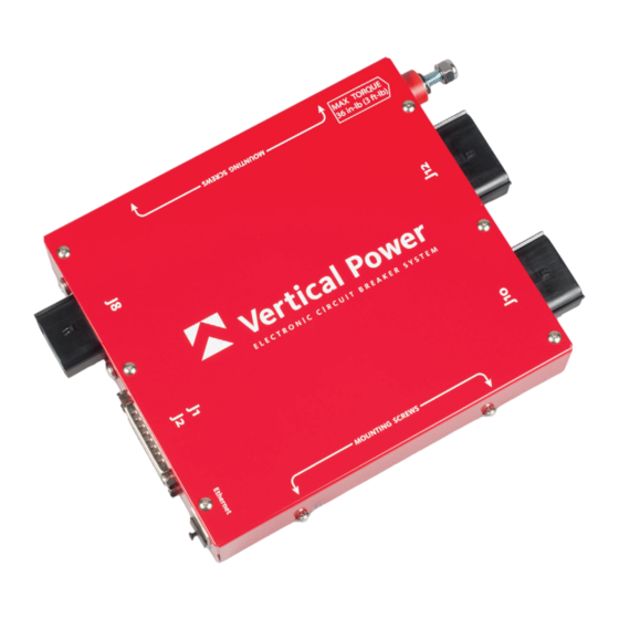
D-sub Connector Be sure to use a momentary up and momentary down flap There are six connectors on VP-X Pro and five on the VP-X Sport. Three of switch (on)-off-(on). Most flap switches come standard in a these connectors, identified as J8, J10, J12 (corresponding with the number non-momentary up configuration on-off-(on). -
Page 18: Installing And Removing Power Connector Terminals
The white insert should never be removed. If it is removed, discard the entire connector. Do not attempt to re-assemble. Contact Vertical Power Support for information regarding replacement connectors. J1 is the top 25 pin d-sub connector and it is male. It mates with a female connector that contains the wiring harness. -
Page 19: Removing Terminals
VP-X Installation and Operating Manual Step 3: With the white insert still in the ‘out’ position, align the terminal to 4.7b Removing terminals rear of connector. Align the orientation feature as shown and insert through Steps 1 & 2: Follow these steps as shown above to raise the white part of appropriate opening. -
Page 20: Pin Removal Tool
VP-X Installation and Operating Manual 4.7c Pin Removal Tool The typical automotive-style voltage regulator does simply that – regulates the voltage to the field wires on the alternator. Varying the field voltage affects A pin removal tool is included with the wiring harness or connector kit. the output capacity of the alternator. -
Page 21: Over-Voltage Planning
VP-X Installation and Operating Manual 4.10 HID Light Considerations 4.8a Over-voltage Planning An over-voltage condition is initiated by a failure in either the voltage HID lights draw about double their normal power during the first 30 seconds regulator or the alternator which causes the voltage to rise above a safe level or so of operation. -
Page 22: Electric Motor Considerations
VP-X Installation and Operating Manual 4.12 Electric Motor Considerations 4. Select the Switches tab and edit the standard switches to match the actual switches in your cockpit. Please read How Switches Are Wired The VP-X is designed to drive the flap and trim motors with special circuits in section 4 of this manual. -
Page 23: What If I Run Out Of Power Pins
VP-X Installation and Operating Manual • Max Amps: The maximum current load that a pin is capable of group items as long as the CB value does not exceed the specs for handling. A load drawing more than this amount of current will fault the smallest wire. -
Page 24: Installation
Consider using a connector for all the control stick wires, so that you up front will make the installation process fairly straightforward. can remove it later if needed. Contact Vertical Power Support for more information on connectors. 5.1 Pre-Installation Tasks •... - Page 25 VP-X Installation and Operating Manual • Do not mount where occupants can easily touch, kick, bump, or otherwise disturb the VP-X. • The wiring harnesses for the VP-X should be secured at a point near the VP-X. Recommended VP-X mounting locations: RV-7, 9, 10: horizontally under the intermediate bulkhead (located between the firewall and instrument panel) using fabricated angle aluminum brackets.
-
Page 26: Wiring Harness Construction
The terminals for (Optional) Contactor alternator output Battery the power connectors require a special crimp tool. Contact Vertical Power Battery Support for availability of this crimp tool. The d-sub wires come in longer Contactor VP-X lengths that you can trim to the desired length and crimp on the pins with standard d-sub crimping tool. -
Page 27: Master Contactor Wiring
VP-X Installation and Operating Manual The diagram below shows what each item is. • Install a 20 AWG wire from the small post of the battery contactor to the master switch. • Connect the other side of the master switch to ground. Master switch •... - Page 28 VP-X Installation and Operating Manual • Install a diode on the starter contactor coil as shown below. Note the With the Primary Power System (PPS) direction of the diode. The starter contactor typically draws about 2 to 4 amps (depending on model) at 14 volts.
-
Page 29: Starter Annunciator Wiring
VP-X Installation and Operating Manual 5.7 Starter Annunciator Wiring 1K Ohm, 1W Resistor Function VP-X Pin Battery VP-X Contactor Starter annunciator input J2-11 J2-11 Batt This pin measures voltage on the starter (or switched) side of the starter contactor and reports it to the EFIS for display. If enabled on the EFIS, an Starter annunciator appears whenever the starter contactor is engaged. -
Page 30: Alternator Wiring
VP-X Installation and Operating Manual 5.9 Alternator Wiring The wiring diagrams below show the use of 20 AWG wire for the alternator field circuit. The VP-X wiring harness use 18 AWG wire. The larger wire The VP-X supports a single or dual alternator system. There are several provides a bit more resilience in the harsh environment of the engine types of alternators that are common among homebuilders, and each is compartment. -
Page 31: Primary Alternator (Plane Power)
VP-X Installation and Operating Manual 5.9b Primary Alternator (Plane Power) configuration, use the switched side of the battery contactor (same as the primary alt). In some installations like an RV-10 where the battery contactor is The Plane Power alternator requires a single wire for the field. It has a built-in in the rear of the aircraft, you can connect the B-lead to the un-switched side voltage regulator. -
Page 32: Backup Alternator (B&C 8 Amp)
VP-X Installation and Operating Manual 5.9d Backup Alternator (B&C 8 Amp) 5.9e Backup Alternator (Plane Power 30 Amp) The B&C SD-8 8 amp alternator requires a single wire to control the relay The Plane Power backup alternator requires a single wire for the field. It has which isolates or connects the SD-8 to the bus. -
Page 33: Alternator - Rotax, Jabiru, Or Ul Power Engines
VP-X Installation and Operating Manual 5.9f Alternator – Rotax, Jabiru, or UL Power engines Contact Vertical Power support for the latest on PPS integration with these three engines. Rotax, Jabiru, and UL Power engines have a built-in alternator/generator with their own regulator that typically mounts on the engine side of the firewall. -
Page 34: Primary Efis Wiring - Power And Data Connections
VP-X Installation and Operating Manual 5.10 Primary EFIS Wiring – Power and Data Connections Use a serial port pair on the EFIS. Make sure the EFIS and the VP-X are wired to the same ground. Do not use the serial ground on the VP-X. The “primary”... - Page 35 VP-X Installation and Operating Manual The diagram below shows wiring diagram detail using 20-24 AWG SV PFD VP-X 3-conductor shielded wire (included in wiring harness kit). 37-Pin J12-9 Power Ground Port 2 RX 5 J1-20 TX 24 AWG wire, Port 2 TX 6 J1-22 RX soldered to shielding J1-21 Ser GND...
-
Page 36: Items You Don't Have To Wire To The Efis
VP-X Installation and Operating Manual a single power wire. DO NOT wire each power pin on the SkyView to the two ground wires together and then run a single wire to the its own power pin on the VP-X. (see diagram below) firewall. -
Page 37: Trim System Wiring
These servos are Wiring” on page 80 of this manual.) designed to run at 14 volts, and the VP-X Pro provides regulated 14v power to the trim motors so they can operate safely in 14v or 28v systems. The... -
Page 38: Pitch Trim Wiring
VP-X Installation and Operating Manual 5.19a Pitch Trim Wiring Roll Trim The trim wires are grouped together by trim function, and shown on the Load Function VP-X Pin Planning worksheet. They are separated from each other by number, but are +2.5 reference voltage (wht/blu) J1-3 physically located next to each other on the connector. -
Page 39: Co-Pilot Disconnect Switch
Follow the diagram below if installing the Trio auto trim module. The diagram is for both 14 volt and 28 volt systems. 5.19f PH Aviation Trim Contact Vertical Power Support for the latest information on using the VP-X Signal Voltage with PH Aviation Trim. -
Page 40: Flap System Wiring
The flap switch has three pins: a common, one to command flaps up and one 5 amps, you must have a VP-X with serial number 1350 to command flaps down. or higher – Contact Vertical Power Support if you need an upgrade. VP-X Flap Motor As of firmware version 1.5 the VP-X also supports RV-10 reflex settings. -
Page 41: Flaps System With Limit Switches
VP-X Installation and Operating Manual Where to mount the POS-12: A flap position sensor can be installed and wired as described above (to The POS-12 should be mounted so that a pushrod can be attached to both show flap position on the EFIS). the POS-12 and to the bell crank on the flap system. -
Page 42: Standard Switches
VP-X Installation and Operating Manual The table below shows the switch inputs and the associated pin. • Wire each switch to an input on the VP-X. • Wire the other terminal on each switch to ground. Use the same Function VP-X Pin ground block as the VP-X ground wiring. -
Page 43: Alternator Switch
VP-X Installation and Operating Manual 5.21c Alternator switch DPDT See PPS installation manual on-on for preferred method If installing a single alternator, the alternator switch can be a simple on/off switch (SPST) wired to one of the inputs. You then associate (in the setup SPST To Battery on-off... -
Page 44: Dual-Function Switch
VP-X Installation and Operating Manual not accidentally turn on in flight. A DUAL SPEED BOOST PUMP MUST BE 5.21f Dimmer wiring WIRED AS SHOWN BELOW: Wire the dimmer in-line between the VP-X and the device, such as a load. Ensure the rheostat is sized appropriately for the electrical load. Use a single power pin set to “always on”... -
Page 45: Lightspeed Ignition Wiring
VP-X Installation and Operating Manual 3A CB 3A CB Switch Input L P-Mag L P-Mag VP-X L P-Mag VP-X Switch 3A CB 3A CB R P-Mag Switch Input R P-Mag R P-Mag Switch P-Lead P-Lead Switch Switch P-Lead P-Lead Switch Switch 2. -
Page 46: Backup Circuit Considerations
VP-X Installation and Operating Manual There are two types of failures to consider. One type of failure occurs on the Main Backup ground and prevents you from flying. The other type of failure occurs while EFIS EFIS you are flying and may be harmless or could require you land at the next opportunity. -
Page 47: Backup Method B
VP-X Installation and Operating Manual 5.24b Backup Method B VP-X Backup capability is the ability to provide power to an electrical device independent of the switching internal to the VP-X. To VP-X power pin Avionics Master To electrical device Switch Device Device To battery... -
Page 48: Do Not Wire Backups This Way
VP-X Installation and Operating Manual Wire a fuse or fuse block near the battery. Size the fuse for the wires and as Doing so may cause unreliable operation and may blow the fuse under per recommended by the EFIS manufacturer. Then wire to an SPST switch. certain circumstances. -
Page 49: Tcw Integrated Back-Up Battery System
VP-X Installation and Operating Manual 5.25 TCW Integrated Back-Up Battery System Option 2: This method uses the IBBS solely as a backup power supply to a device that The TCW Integrated Back-Up Battery System (IBBS) can be used with the has dual power inputs (like most EFIS displays). -
Page 50: Tcw Ibbs 3/6Ah Wiring
VP-X Installation and Operating Manual 5.25b TCW IBBS 3/6ah Wiring Starter Battery There are two ways to wire the TCW IBBS 3/6ah, depending on if the Contactor Contactor protected device has one or two power inputs. Batt Pin 5 is used to charge the internal IBBS battery. Pin 6, 7, 8 are used as power source for the devices wired to pins 12-15. - Page 51 VP-X Installation and Operating Manual There are several ways to wire an aux battery, depending on your Option 2: application. You can install an aux battery contactor to connect or isolate the The diode is used to charge the aux battery when the master switch is on. aux battery from the main bus.
-
Page 52: Aux Battery Wiring And Voltage Measurement
5.27 Aux Battery Wiring and Voltage Measurement Please follow the latest AeroLEDs instructions with regard to shielding and case grounding. Please see Appendix E in this manual for detailed This section applies to the VP-X Pro only. information regarding wiring AeroLEDs. Function... -
Page 53: Retractable Gear Wiring
VP-X Installation and Operating Manual 5.30 Retractable Gear Wiring When I measure a pin that is “off” with a digital multimeter, I The VP-X provides a source of circuit protected power for the gear switch. get a voltage reading. Is this normal? Wire the gear system per the airframe manufacturer’s instructions. - Page 54 VP-X Installation and Operating Manual • Using the fuse-protected test lead, connect one wire to the positive • Using an ohm meter or test lamp, verify each of the pins coming from terminal of a battery (any battery is OK as long as it matches the a panel switch is grounded when the switch is turned on.
-
Page 55: Configure The System Settings
VP-X must be done using the VP-X configurator. The EFIS itself must be configured to recognize and work with the VP-X Pro and Sport. 6.2 Configuring the GRT EFIS Note that you can configure the VP-X as a standalone unit – you The GRT EFISs include full setup menus for the VP-X (original version) but do not necessarily need the EFIS to be connected. -
Page 56: Configuring The Garmin G3X Efis
1. Under COMM page in the setup, set the MFD serial port that is current if you have shunts installed. You can display or hide these connected to the VP-X Pro or Sport to “Vertical Power”. values. To hide them, select “other” for the shunt location in the VP-X setup. -
Page 57: Device Configuration (Starter, Avionics, Lights, Etc.)
VP-X Installation and Operating Manual 6.8 Device Configuration (Starter, Avionics, Lights, etc.) 6.10 System Configuration (Over-voltage and Backup Alternator) In the VP-X Configurator, go to Device Configuration. Each device (lights, The primary alternator is configured using a unique setup screen. transponder, radio, EFIS, etc.) that is powered by the VP-X must be enabled •... -
Page 58: Wig-Wag Configuration
VP-X Installation and Operating Manual 6.11 Wig-Wag Configuration 6.12 Trim Configuration In the VP-X Configurator, go to Wig Wag Configuration. In the VP-X Configurator, go to Pitch Trim Configuration. Follow the instructions below and repeat for roll trim. XeVision HID light customers: The VP-X includes a license to use the patented XeVision warm up and pulsing algorithms and therefore the VP-X You can run the trim from both a trim switch as well as from the VP-X wig wag will not void the XeVision warranty. -
Page 59: Flaps Configuration
VP-X Installation and Operating Manual 6.13 Flaps Configuration The following trim items can be configured: In the VP-X Configurator, go to Flaps Configuration. You can run the flaps Motor Standard/Inverted. Press the Up or Down buttons on the from both the flap switch as well as from the VP-X Configurator. polarity Configurator, and the trim should move in the appropriate direction. - Page 60 VP-X Installation and Operating Manual Motor Standard/Inverted. Press the Up or Down buttons, and the Up limit Run the flaps all the way up using the Up soft key. Note polarity flaps should move in the appropriate direction. If not, change the number that shows the flap position (should be on the the polarity until the flaps run in the correct direction.
- Page 61 VP-X Installation and Operating Manual End Point Only applies if Flap Control is set to Position. Time in Flaps Up Flaps Up Extent seconds that the flaps will run extra when at the top and Overspeed position Overspeed position bottom travel limits. This is to eliminate the slop inherent in the position sensor, which is used to stop the flaps at the Flaps 20 Flaps 20...
-
Page 62: Export Settings
VP-X Installation and Operating Manual 6.14 Export Settings As you run the flaps, the position number changes. The number should change throughout the entire range of flap motion. If it does Save your settings to your PC. Go to the File menu, then Save Configuration not, then the position sensor is binding at the ends and you should As... -
Page 63: Ground Test
VP-X Installation and Operating Manual 7. Ground Test Prolonged low-power operation of a new engine may adversely affect the engine. Be sure you understand the engine break-in requirements, and The ground test steps are performed in two parts: the first part without the balance those against the time needed to test the electrical system. -
Page 64: Flight Test
VP-X Installation and Operating Manual 8. Flight Test 8.2 VP-X system checkout Now that initial aircraft checkout flights are complete, you can proceed with This section verifies the proper operation of the VP-X during flight. the electrical system tests. Prior to flight, make sure you understand the following, which is described in Once airborne, keep an eye out for traffic and obstacles during the test the Operating section: procedure. -
Page 65: Troubleshooting
Follow these instructions for each system. want to use the ‘Position’ mode, then the position values are used to Please contact Vertical Power Support at 425.328.1658 if you have any stop the flap motor at the top, middle, and bottom positions. - Page 66 VP-X Installation and Operating Manual Flaps work in momentary but do not work when set to position Problem Solution (intermediate flap stops). Flaps go up, • Run the flaps using Momentary and verify they operate Please follow these steps carefully in the order shown: but not quite correctly through the whole range.
-
Page 67: Electrical Configuration
9.4 “Cannot Connect” error when using VP-X Configurator Please see the Configurator Release Notes document for troubleshooting instructions. The release notes are available on the Vertical Power website at www.verticalpower.com under Help and then Software. Rev. D (August 5, 2020) -
Page 68: Vp-X System Operation
VP-X Installation and Operating Manual 10. VP-X System Operation • View the current draw, in amps, of each circuit. The minimum detectable amount is 100 mA (1/10 of an amp). This section describes the operation of the VP-X. Additional details can be •... -
Page 69: Trim Switch Fault Detection On Startup
VP-X Installation and Operating Manual When you press the flap up switch, the flaps go all the way up unless you For example, if the pitch trim begins to “run away,” hold down the opposite press the flap down switch to stop them mid-stream. On some aircraft, you pitch trim switch (a natural reaction, by the way) until the fault shows on the can set the reflex position to the top position, the 0 deg position to the first screen. -
Page 70: Continuous Flaps
VP-X Installation and Operating Manual 10.8 Starter Disable 10.5f Continuous Flaps When enabled, you can command flaps past the next flap down stop before The starter circuit is normally on, meaning the starter switch has power at all the flaps stop. times when the engine is not running. -
Page 71: Data Comm Loss
VP-X Installation and Operating Manual 10.13 Data Comm Loss 10.14 Firmware Updates If the data bus between the VP-X and the EFIS fails, the VP-X will continue Firmware updates are performed using the PC-based Configurator to operate normally and provide circuit protection. However, any data Application. -
Page 72: Appendix A - Pinout Diagram
VP-X Installation and Operating Manual Appendix A – Pinout Diagram System Name Bank Amps Range Physical Pin Flap 1-10 J12-5 & 6 Starter A or B 1-10 J10-1 EFIS J12-9 Field_Pri J12-11 5A-1 J8-1 5A-2 J8-3 5A-3 J8-4 5A-4 J8-5 5A-5 J8-6 5A-6... -
Page 73: Appendix A1 - J8, J10, J12 Connector Wiring
VP-X Installation and Operating Manual Appendix A1 – J8, J10, J12 Connector Wiring VP-X Device (5A CB max) Device (10A CB max) Device (5A CB max) Device (5A CB max) Device (5A CB max) Device (5A CB max) Device (5A CB max) Device (5A CB max) Male VP-X... -
Page 74: Appendix A2 - J1 Connector Wiring
VP-X Installation and Operating Manual Appendix A2 – J1 Connector Wiring VP-X Device (2A CB max) Device (2A CB max) Roll Trim WHT/BLU Roll Trim WHT/ORN Ray Allen WHT/GRN Roll Trim Trim motor w/ pos sensor Roll Trim Roll Trim WHT/BLU Pitch Trim WHT/ORN... -
Page 75: Appendix A3 - J2 Connector Wiring
VP-X Installation and Operating Manual Appendix A3 – J2 Connector Wiring VP-X Switch input 1 Switch input 2 Switch input 3 Switch input 4 Switch input 5 Switch input 6 Switch input 7 Switch input 8 Switch input 9 Switch input 10 Starter annun input From switched side of starter contactor Aux batt voltage input... -
Page 76: Appendix B - Wiring Harness Contents
VP-X Installation and Operating Manual Appendix B – Wiring Harness Contents The following wire types and lengths are included in the VP-X Pro wiring harness kit (VP-X Sport does not have components for the J8 connector): Gauge Length (ft) Color... -
Page 77: Appendix C - Vp-X System Annunciators
VP-X Installation and Operating Manual Appendix C – VP-X System Annunciators The following VP-X annunciators are displayed on the EFIS: Alarm Description TRIM RUNAWAY The trim switches are disabled because: 1 - Opposite trim switches were active for at least 3 seconds. The fault can be cleared from the EFIS. -
Page 78: Appendix D - Vp-X Dimensions And Weight
Optional mounting tray available. 9.147 1.705 4X #6-32 Screw 2X Mounting Bracket Weight: VP-X Pro: 2.1 lb (1.0 Kg) *weight does not include mounting VP-X Sport: 1.8 lb (0.8 Kg) brackets or mating connectors Rev. D (August 5, 2020) Page 78... -
Page 79: Appendix E - Aeroled Wiring Tips
VP-X Installation and Operating Manual Appendix E – AeroLED Wiring Tips Here is some information that should be helpful to builders installing AeroLEDs wingtip lights: LED strobes operate differently than legacy Xenon strobes. Legacy Xenon strobes use a flash capacitor that charges up continuously between flashes, pulling a steady amount of current (current is continuously pulsating at the frequency of the charge pump, typically 10’s of kilohertz), then dump the charge to the Xenon tube in a single burst. -
Page 80: Appendix F - Ray Allen Stick Grip Wiring
VP-X Installation and Operating Manual Appendix F – Ray Allen Stick Grip Wiring Excerpt from Ray Allen G205 and G207 stick grips wiring instructions, modified to show VP-X integration. WIRING STYLE 2 (contʼd.) Figure 2C Pilot's Grip Copilot's Grip Switch Switch Switch Switch...
Need help?
Do you have a question about the VP-X Pro and is the answer not in the manual?
Questions and answers
Every thing works except for the landing lights!
The landing lights on the Vertical Power VP-X Pro may not be working due to incorrect configuration or wiring. The VP-X controls landing lights and can alternate power to create a wig-wag or pulsing effect. If the lights are not functioning, check the following:
1. Ensure the lights are properly wired to the VP-X.
2. Verify that the configuration settings in the VP-X allow the lights to operate as expected.
3. Confirm that the external power source is correctly connected.
4. If using LED landing lights with a built-in wig-wag function, disable that feature and use the VP-X wig-wag function instead.
5. Check for any system errors or power supply issues.
If the issue persists, further troubleshooting or contacting Vertical Power tech support may be necessary.
This answer is automatically generated