
Summary of Contents for Trek 156A
- Page 1 OPERATOR’S MANUAL MODEL 156A CHARGED-PLATE MONITOR 上海汇分电子科技有限公司 上海市闸北区天目西路511号锦程大厦1408室 联系方式:400-660-9565 网站:www.19mro.com 1445/JRB...
- Page 3 Thank you for buying a Trek instrument. This instrument has been designed and built to high standards to give you years of trouble-free service. If you have any questions, please feel free to contact your Trek Representative at: Write: TREK, INC.
-
Page 5: Table Of Contents
Safety ........iii Safety Precautions for the Model 156A ..... v Preface . - Page 6 Section V Maintenance Safety Precautions for the Model 156A ..... . Battery Pack Maintenance ......
-
Page 7: Safety
Do Not Operate Without Covers To avoid electric shock or fire hazard, do not operate this instrument with the covers removed. Fuses There are no user serviceable fuses inside this unit, please refer all problems to Trek, Inc. or an authorized Trek service center. - Page 8 Safety Safety Precautions (cont.) Indoor Use Only This instrument is intended for indoor use only. Do Not Operate in Wet or Damp Conditions To avoid electric shock, do not operate this instrument in wet or damp conditions. Do Not Operate in an Explosive Environment To avoid injury or fire hazard, do not operate this instrument in an explosive environment.
- Page 9 Safety Safety Terms and Symbols Terms in the Manual These terms may appear in this manual: Warning: Warning statements identify conditions or practices that could result in injury or loss of life. Caution statements identify conditions or practices that could result in Caution: damage to this product or other equipment.
-
Page 10: Safety Precautions For The Model 156A
Model 156A: 1. Refer all maintenance procedures to qualified personnel. 2. Prior to performing maintenance procedures, turn off the 156A and disconnect the battery charger/eliminator from its power source. Failure to observe this precaution could result in an electrical shock. -
Page 11: Preface
Preface This manual provides user information for the Model 156A Charged-Plate Monitor and contains the following chapters and appendixes: • Introduction contains a brief product description and describes an incoming confidence test for the unit. contains initial setup information for the Model 156A. - Page 12 viii...
-
Page 13: Section I Introduction
This manual provides instructions to install and operate the Trek Model 156A Charged-Plate Monitor. We recommend you take the time to read this manual to take full advantage of the features and benefits of the instrument. -
Page 14: Modes Of Operation
START voltage. The time required to discharge the ion collecting plate from the programmed START voltage to the programmed STOP voltage is measured by the Model 156A. The discharge is due to ‘incident ion flow’ on the ion collecting plate. -
Page 15: Incoming Confidence Test
Do not turn on the 156A until instructed to do so. To do so before the Warning: appropriate point in time could result in an electrical shock and/or damage to the instrument. - Page 16 STOP voltage’ on page III-5 for information on changing the decay stop voltage.) At the programmed stop voltage the decay timer will stop and the decay time will be indicated on the DECAY TIME display. This completes the incoming confidence test. Turn OFF the 156A. I - 4...
-
Page 17: Section Ii Installation
Please contact TREK, Inc. or an authorized service organization for battery replacement information. Battery Charger/Eliminator Connection The Model 156A is designed to be battery operated or operated while connected to a line voltage source. A battery charger/eliminator is available for all nominal line voltages. -
Page 18: Initial Setup Connections
Before operating the Model 156A, the following connections should be made: Ground Connection The Model 156A must be connected to a solid ground reference to ensure accurate and repeatable measurements. All voltage measurements will be made with respect to this ground reference point. The power to the unit should be OFF when connecting the ground on the rear panel of the unit to a ground reference. -
Page 19: Section Iii Operation
Warning: The Model 156A is battery operated and high-voltage may be present at the ion collecting plate or ion plate connector whether or not the battery charger/eliminator is connected to the rear panel when the POWER switch is... -
Page 20: Front Panel Features
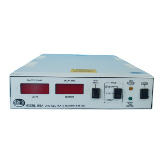
POWER DECAY FLOAT VOLTS SECONDS DECAY FULL MODEL 156A CHARGED PLATE MONITOR SYSTEM CHARGE Figure 3-2: Front Panel Features (cont.) This digital display indicates the plate voltage in PLATE VOLTAGE Display: volts. This digital display indicates the time in seconds for the 6. -
Page 21: Rear Panel Features
5. ION COLLECTING PLATE Receptacle: This BNC receptacle is for connection of the ion collecting plate. The Model 156A is battery operated and high-voltage may be present at Warning: the ion collecting plate or ion plate connector whether or not the battery charger/eliminator is connected to the rear panel when the POWER switch is ON. -
Page 22: Float Mode Operation
Operation FLOAT Mode Operation In the FLOAT mode, the 156A monitors the voltage on the plate caused by air ion imbalance. 1. Place the ion collecting plate in the area to be monitored. 2. Place the MODE switch in the FLOAT mode. -
Page 23: Programming Operation
Operation Programming Operation The Model 156A can be operated in any one of three modes, the (+) DECAY mode, the (-) DECAY mode, and the FLOAT mode. When the instrument is first turned on, it will indicate the revision level of the Note: program in the DECAY TIME display. -
Page 24: Programming The Stop Voltage
STOP voltages and resets itself to begin testing for the newly chosen parameters. The 156A will display the ‘revision level’ of the command program and then will flash the new START voltage in the PLATE VOLTAGE display and the new STOP voltage in the DECAY TIME display. -
Page 25: Monitoring The Plate Voltage Using The Output Monitor
Operation Monitoring the Plate Voltage using the Output Monitor The OUTPUT MONITOR receptacle provides a low-voltage replica of the plate voltage. The OUTPUT MONITOR voltage is 1/200th of the plate voltage. The OUTPUT MONITOR can be connected to an oscilloscope for visual representation of the ion tests. - Page 26 III -8...
- Page 27 Section IV Model 156A Specifications DANGER: This instrument is not rated for use in an explosive environment. DO NOT use it an explosive environment or an explosion may result. PERFORMANCE Monitored Voltage Range 0 to ±1100 V DC or peak AC.
-
Page 28: Section Iv Specifications
Specifications Specifications (cont.) PERFORMANCE (cont.) Decay Mode Thresholds (cont.) Stop Voltage Programmable from 0 to 999 V in 1 V increments. Within ±1 V of programmed stop voltage. Stop Accuracy Plate Self-Discharge Less than 12 V/minute. (unpolarized) FEATURES A two-position rocker switch. Power On/Off Test/Reset Control A momentary toggle switch used in... - Page 29 Specifications Specifications (cont.) FEATURES (cont.) 3 ½ digit red LED display. Plate Voltage Digital Panel Meter Range 0 to ±1100 V. Resolution 1 volt. Better than 0.1% of full scale, ±1 count. Accuracy Decay Time Digital Panel Meter 4-digit red LED display. Range 0 to 9999 seconds.
- Page 30 Specifications (cont.) GENERAL Power Requirements Battery Eliminator/Charger Optionally available for all nominal line voltages. Contract Trek, Inc. or an authorized service organization for more information. NOTE: If line impulses exceed 500 V when using the battery eliminator/charger, the unit may reset and require operator...
- Page 31 Specifications Specifications (cont.) MECHANICAL Instrument Dimensions 83 mm H x 318 mm W x 280 mm D (3.25" H x 12.5" W x 11" D). Instrument Weight 2 kg (4.4 lb). Voltage Monitor Connector BNC coaxial connector. (3 meter length, maximum.) Ground Receptacle Banana jack.
- Page 32 Specifications Specifications (cont.) Certification and Compliance TREK, INC. certifies that each Certification Model 156A is tested and calibrated to specifications using measurement equipment traceable to the National Institute of Standards and Technology or traceable to consensus standards. A Certificate of Calibration accompanies each instrument when it is shipped from the factory.
-
Page 33: Section V Maintenance
Cycling of the battery pack can be accomplished by following the procedure below. 1) Plug the battery eliminator/charger into the Model 156A. 2) Charge the battery pack until the “Full Charge” indicator on the Model 156A is illuminated. 3) Remove the charger from the Model 156A. -
Page 34: Battery Pack Maintenance
5) Leave the Model 156A “ON” for more than 12 hrs. 6) Plug the battery eliminator/charger into the Model 156A. 7) Charge the battery pack until the “Full Charge” indicator on the Model 156A is illuminated. 8) Cycling is completed. -
Page 35: Service Information
The warranty is voided if the instrument is serviced within the warranty period by anyone other than Trek, Inc. or one of its authorized service organizations. In the event of a malfunction, and the instrument must be returned for repair: 1. - Page 37 Model 156P C25x25-S3M (1 x 1 ) ....17375 SPECIAL PLATES Contact TREK, INC. or an authorized sales organization for applications that require a different size or shape ion collecting plate.
- Page 39 Appendix B Warranty Statement New instruments sold by TREK, INC. (hereinafter called the “Company”) are warranted only as stated below: Subject to the exceptions and upon the conditions specified below, the Company agrees to correct, either by repair, or in the Company’s sole discretion, by replacement, any defect of...
- Page 41 Please go to our web site: www.trekinc.com for a complete list of our sales and service representatives and distributors located in the United States and throughout the world. Trek Contact Information: TREK, INC. 190 Walnut Street Lockport, NY 14094-3710 USA...
- Page 42 上海汇分电子科技有限公司 上海市闸北区天目西路511号锦程大厦1408室 联系方式:400-660-9565 网站:www.19mro.com...
Need help?
Do you have a question about the 156A and is the answer not in the manual?
Questions and answers