Table of Contents
Advertisement
Quick Links
Advertisement
Chapters
Table of Contents

Summary of Contents for Lutz Jesco Easychlorgen 4250
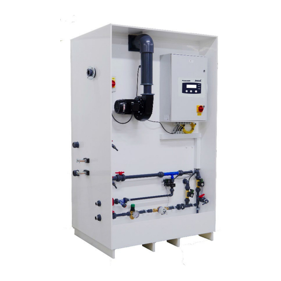
- Page 1 EASYCHLORGEN 4250, 8500 Electrolysis system for on-site hypochlorite generation Installation, Operation & Maintenance Instructions Read these operation and maintenance instructions before start-up! To be held for further reference. v1.0 11/2017...
- Page 2 2 | Installation, Operation & Maintenance Instructions EASYCHLORGEN...
-
Page 3: Table Of Contents
Table of Contents _____________________________________________________________________________________________ Contents 10.3 R ............. 40 EMOTE NHIBIT 10.4 S ..........40 OFTENER EGENERATION 1. NOTES FOR THE READER ..........4 10.5 E ..........41 MERGENCY HUTDOWN 10.6 R ........... 41 ECORD OG OF PERATION 1.1 I ..............4 NTRODUCTION 1.2 E ........4... -
Page 4: Notes For The Reader
Chapter 1: General _________________________________________________________________________________________ 1. Notes for the Reader 1.4 Identification of warnings Warnings are intended to help you recognize risks and avoid 1.1 Introduction negative consequences. This operating manual provides significant assistance in the This is how warnings are identified:- successful and smooth running of the EASYCHLORGEN electrolysis systems, also referred to, in short, as “system”... -
Page 5: Instruction & Training Course Assistance
If the operating personnel still require further training after the system has been delivered to the operator, please contact Lutz- Jesco. 1.9 Example of training course topics... - Page 6 Chapter 1: General _________________________________________________________________________________________ Confirmation of the training instruction Topic of the training instruction: __________________________________________________________________________________________________ __________________________________________________________________________________________________ Date: _____________________________________________________________________________________________ Training instructor: __________________________________________________________________________________________________ Training instructor’s signature: __________________________________________________________________________________________________ Surname First Name Signature 6 | Installation, Operation & Maintenance Instructions EASYCHLORGEN...
-
Page 7: Safety
Chapter 2: Safety ___________________________________________________________________________________________ 2. Safety 2.2 Hazards due to non-compliance with the safety instructions 2.1 General warnings Failure to follow the safety instructions may endanger not only persons, but also the environment and the device. The following warnings are intended to help you to eliminate the dangers that can arise while handling the device. - Page 8 Chapter 2: Safety ___________________________________________________________________________________________ 2.5.4 Personnel tasks knowledge of safety equipment and the way this equipment functions In the table below, you can check what personnel qualifications knowledge of these operating instructions, particularly are the pre-condition for the respective tasks. Only people with of safety instructions and sections relevant for the appropriate qualifications are allowed to perform these tasks! activity...
-
Page 9: Intended Use
• Iron (Fe) mg/kg <10 qualified to carry out their respective activities. Mercury (Hg) mg/kg <0.26 No original spare parts or accessories of Lutz-Jesco are • Nickel(Ni) mg/kg <13 used. Unauthorised changes are made to the device. • Manganese (Mn) mg/kg <0,5... -
Page 10: Product Description
Chapter 4: Product description _________________________________________________________________________________________ 4. Product description Hot climates: In hot climates where water supply temperatures may exceed 20°C, an external water chiller (supplied by 4.1 Scope of delivery others) should be installed on the incoming water supply. The water chiller must be correctly sized according to the liquid Please compare the delivery note with the scope of delivery: output capacity of the model (refer to 5.1.1), the ambient air... - Page 11 Chapter 4: Product description _________________________________________________________________________________________ 4.2.2 EASYCHLORGEN description Item Description Control panel display Brine venturi Brine solenoid valve Dilution solenoid valve Chilled water solenoid valve Water meter Pressure regulating valve Product sample tap Air blower Air-flow sensor System run/stop level switch Temperature probe Electrolyser Product de-gassing tank...
- Page 12 Chapter 4: Product description _________________________________________________________________________________________ 4.2.3 Power supply description A dedicated, stand-alone power supply unit (PSU) is provided. The operation of the main isolator (4) will disconnect power to The PSU cabinet provides power for the whole of the all circuits within the PSU cabinet. electrolyser system;...
- Page 13 Chapter 4: Product description _________________________________________________________________________________________ 4.2.4 Function sequence in automatic operation Power On (start-up) Normal Operation Fault Condition * The Start Delay timer can be set in the engineer’s menu to prevent frequent stop/starting of the generating cycle once the product tank is full (default setting 60 minutes).
- Page 14 Chapter 4: Product description _________________________________________________________________________________________ 4.2.5 Rating Plate The rating plate contains information on the safety and functional method of the product. The rating plate must be kept legible for the duration of the service life of the product. Description Product name Nominal size Month/ year of manufacture...
-
Page 15: Technical Data
Chapter 5: Technical data _________________________________________________________________________________________ 5.1.6 Components in contact with the media 5. Technical data Description [all models] Material 5.1 EASYCHLORGEN skid unit PVC, titanium, PTFE, Electrolytic cell 5.1.1 Output data Product transfer pipe Product tank MDPE Model: 4250 8500 Product tank level switch 4.25 Chlorine capacity... -
Page 16: Dimensions
Chapter 5: Technical data _________________________________________________________________________________________ 5.2.3 Other data Model: 4250 8500 Net weight 6. Dimensions All dimensions in mm. 6.1 EASYCHLORGEN 4250/8500 Description Product outlet connection DC power busbar connection (-ve) Acid wash inlet connection DC power busbar connection (+ve) Acid wash outlet connection Brine inlet connection Water inlet connection... -
Page 17: Intermediate Brine Tank
Chapter 6: Dimensions __________________________________________________________________________________________ 6.2 Intermediate brine tank Plan elevation Side elevation 6.3 Power Supply Unit (PSU) cabinet Rear elevation Side elevation 17 | Installation, Operation & Maintenance Instructions EASYCHLORGEN... -
Page 18: Installation
Chapter 7: Installation __________________________________________________________________________________________ 7. Installation The system must be accessible for operation and maintenance. Refer to installation schematics, section 7.4. WARNING Perform the following steps:- Increased risk of accidents due to insufficient Locate the skid unit into its intended permanent position qualification of personnel! allowing sufficient space to connect services to the connection ports to the side and top of the system. -
Page 19: Hydraulic Installation
Chapter 7: Installation __________________________________________________________________________________________ The PSU fan ventilator lower inlet grille and upper exhaust 7.2 Hydraulic installation grilles must not be obstructed. Allow a minimum of 400mm (3ft) clearance from any nearby wall/surface. 7.2.1 Cold feed water supply The PSU must be bolted firmly at its base to the floor or plinth on which it is positioned. - Page 20 Chapter 7: Installation __________________________________________________________________________________________ 7.2.4 Intermediate brine tank Perform the following steps:- The intermediate brine tank is vitally important to maintain a Install 25mm (1”) pipework to the 1”BSPm threaded softener steady supply of brine to the EASYCHLORGEN skid system. raw water inlet of the duplex softener valve head.
- Page 21 Chapter 7: Installation __________________________________________________________________________________________ 7.2.6 Ventilation It is advisable to provide the following warning signs in the plant room and exterior vent point: DANGER! Warning Sign • No Smoking • Danger to life through explosions! No Naked Flames • Precondition for action: Incorrect installation of the ventilation exhaust piping may cause irreversible damage to the system components and may even ...
-
Page 22: Electrical Installation
Chapter 7: Installation __________________________________________________________________________________________ 7.3 Electrical Installation A 3C+E cable is factory fitted for this purpose and may be replaced to comply with local regulatory requirements. Interconnect the multi-core signal cable from the PSU cabinet to the EASYCHLORGEN control panel. A multi-core DANGER! cable is factory fitted for this purpose and may be replaced to comply with local regulatory requirements. - Page 23 Chapter 7: Installation __________________________________________________________________________________________ BUSBAR SQUARE FLAT CONNECTOR PLATE ASSEMBLY Using a torque wrench and 13mm socket, tighten the four bolts evenly to 4Nm. If the equipment is situated in a location where background vibration may be present, apply a thread-lock sealant (e.g. Loctite 290) to the bolt threads during the final tightening turns.
- Page 24 Chapter 7: Installation __________________________________________________________________________________________ 7.3.3 EASYCHLORGEN Control Panel PCB Terminal List Terminal Function signal input Common 0V I.D. Description Sig Tank degassing tank signal Start/Stop input Mains Out (auxiliary mains output) Common 0V Sig Ext Tank Signal for product tank 110Vac 50/60Hz input Run/Stop run/stop switch...
- Page 25 Chapter 7: Installation __________________________________________________________________________________________ 7.3.4 Control Panel PCB Terminal Diagram 25 | Installation, Operation & Maintenance Instructions EASYCHLORGEN...
- Page 26 Chapter 7: Installation __________________________________________________________________________________________ 7.3.5 4250/8500 Power Supply Cabinet: Component Layout & Information 26 | Installation, Operation & Maintenance Instructions EASYCHLORGEN...
- Page 27 Chapter 7: Installation __________________________________________________________________________________________ 7.3.6 4250 Control Panel to Power Supply Cabinet Connections 27 | Installation, Operation & Maintenance Instructions EASYCHLORGEN...
- Page 28 Chapter 7: Installation __________________________________________________________________________________________ 7.3.7 4250 Power Circuit Wiring Schematic 28 | Installation, Operation & Maintenance Instructions EASYCHLORGEN...
- Page 29 Chapter 7: Installation __________________________________________________________________________________________ 7.3.8 8500 Control Panel to Power Supply Cabinet Connections 29 | Installation, Operation & Maintenance Instructions EASYCHLORGEN...
- Page 30 Chapter 7: Installation __________________________________________________________________________________________ 7.3.9 8500 Power Circuit Wiring Schematic 30 | Installation, Operation & Maintenance Instructions EASYCHLORGEN...
-
Page 31: General Installation Layouts
Chapter 7: Installation __________________________________________________________________________________________ 7.4 General installation layouts 7.4.1 Electrolytic plant Installation layout example 1: Electrical PSU room and Electrolysis 31 | Installation, Operation & Maintenance Instructions EASYCHLORGEN... - Page 32 Chapter 7: Installation __________________________________________________________________________________________ Installation example 2: Single plant room facility 7.4.2 Softening equipment layout 32 | Installation, Operation & Maintenance Instructions EASYCHLORGEN...
- Page 33 Chapter 7: Installation __________________________________________________________________________________________ Table of key descriptions Description Hydrogen gas detector Product tank natural ventilation pipe work Product tank Chlorine dosing equipment example Electrolyser forced ventilation pipe work EASYCHLORGEN unit PSU cabinet Saturator for electrolysis Potable softened water supply Saturator isolation valve Intermediate brine tank isolation valve Intermediate brine tank...
- Page 34 Chapter 7: Installation __________________________________________________________________________________________ 7.4.3 General installation arrangement Example floor plan: 34 | Installation, Operation & Maintenance Instructions EASYCHLORGEN...
-
Page 35: Control
Chapter 8: Control 8. Control Symbol representation: 8.1 Control display System healthy (GRN) The operation of the EASYCHLORGEN electrolytic chlorine generation and preparation system is performed via the universal System warning /Maintenance action (AMB) EASYCHLORGEN control panel. System fault (flashing RED) The display screen will always describe the system status or fault condition in conjunction with the appropriate LED symbol representation:-... -
Page 36: Start Up
Chapter 9: Start-Up 9.1 Commissioning and Initial Start-Up Precondition for action: WARNING The system is configured according to the factory setup. Risk of equipment failure and injury to personnel and property! The system has been installed in accordance with section 7, Installation. - Page 37 Chapter 9: Start-Up 9.1.3 Exiting Program volume of brine solution prior to automatically starting normal generation/batch cycles. Scroll UP until Program 1 / End Program Mode is Note that the PSU GEEN lamp will be illuminated reached. At this point press ENTER and the display will indicating the EASYCHLORGEN system is in normal return to the MANUAL INHIBIT screen.
- Page 38 Chapter 9: Start-Up 9.1.4 Changing display language — Carry out a chlorine product strength test. The 10. The control panel display language can be selected result should ideally be 0.6% +/- 0.1%. when the EASYCHLORGEN is in normal operation simply by scrolling down to Program 9 and repeatedly —...
-
Page 39: Commissioning And Initial Start
Chapter 9: Start-Up 9.2 Normal Start-Up When the countdown is complete the EASYCHLORGEN will resume normal operation and display SYSTEM HEALTHY, GENERATING:- Precondition for action: The EASYCHLORGEN has only been in short term shutdown and that all commissioning and initial start-up procedures have previously been completed and no alterations to the EASYCHLORGEN equipment and configuration has not subsequently been altered. -
Page 40: Operation
Chapter 11: Shutdown __________________________________________________________________________________________ 10. Operation Whilst the system is displaying SYSTEM STOPPED, the scroll UP key may be pressed for 5 seconds to place the system into MANUAL INHIBIT mode which halts the automatic operation:- Note Damage to the system due to incorrect salt supply! Failure to observe the correct specification of salt with this system will most likely result in failure of the system and affect the warranty conditions. -
Page 41: Emergency Shutdown
Chapter 11: Shutdown __________________________________________________________________________________________ 10.5 Emergency Shutdown In the event of an emergency, you must immediately disconnect the device from the mains supply. An Emergency Stop device is fitted at the PSU cabinet front door This device can be operated to stop the system. At the control panel, the screen will display SHUTDWON - EMERGENCY STOP and will activate the alarm condition, indicated by the panel flashing RED lamp and any connected... -
Page 42: Shutdown
Chapter 11: Shutdown __________________________________________________________________________________________ 11. Shutdown Temperatures between +0°C and +50°C Relative air humidity must not exceed 90% 11.1 Short-term shutdown (up to 6 months) 11.4 Transportation Perform the following working steps:- Required actions:- During normal operation, isolate the power supply to the EASYCHLORGEN via the rotary isolator switch on the The system has been shut down in accordance with the ... -
Page 43: Maintenance
12.1.1 Clean/replace brine strainer screen Depending on quality of the softened cold water supply and salt Products by Lutz-Jesco are manufactured to the highest quality specification, the in-line strainer screen protecting the brine standards and have a long service life. However, some parts are control solenoid valve may periodically require cleaning or subject to operational wear. - Page 44 Chapter 12: Maintenance _________________________________________________________________________________________ 12.1.4 Replace product pipe seals/gaskets Elastomers (rubber seals) exposed to the electrolytic process are subject to chemical wear and require routine replacement every two years regardless of operating hours as a preventative PRV ASSEMBLY maintenance action. Prior to commencing this maintenance action, the electrolytic hydraulic circuit requires purging of residual chlorine solution.
- Page 45 Chapter 12: Maintenance _________________________________________________________________________________________ 12.1.5 Hydrogen gas detector inspection 12.1.6 Major service The hydrogen gas (H ) detection system is very important to Note ensure a safe environment. The H detector should be routinely tested at least annually, to verify a safe system of work. Damage to the system due to incorrect maintenance! N.B.
-
Page 46: Electrolyser Cleaning
Chapter 12: Maintenance _________________________________________________________________________________________ 12.2 Electrolyser cleaning The electrolyser (electrolytic cell assembly) may require acid cleaning periodically to remove the presence of water hardness scaling and any heavy metal deposition e.g. iron and manganese deposits. Cleaning of the electrolyser can be 3 WAY L-PORT VALVE ADJUSTMENT EXAMPLE automated or carried out manually, depending on client indicators show flow and return through the electrolyser... -
Page 47: Finishing Maintenance
Chapter 12: Maintenance _________________________________________________________________________________________ 12.3 Finishing maintenance Perform the following working steps:- Make a note of the date and scope of the maintenance performed. Complete any operational, service or commissioning log sheets associated with the EASYCHLORGEN system and as per any associated documents which are contained within this manual. -
Page 48: Location Of Maintenance Parts
Chapter 12: Maintenance _________________________________________________________________________________________ 12.4 Location of maintenance parts 12.4.2 Right side electrolyser compartment 12.4.1 Left side electrolyser compartment Detail A: Detail C: Detail B: Detail D: Detail E: 48 | Installation, Operation & Maintenance Instructions EASYCHLORGEN... - Page 49 Chapter 12: Maintenance _________________________________________________________________________________________ Detail F: Table: Maintenance Parts List Item description (detail A – H) DN25 Union O-ring DN15 NRV O-ring DN15 Union O-ring DN40 Union O-ring DN40 Adaptor Gasket DN25 Valve O-ring DN20 Strainer Screen DN20 PRV strainer screen 12.4.3 Hydraulic control apparatus Detail G: Detail H:...
-
Page 50: Trouble-Shooting
Chapter 13: Trouble-shooting _________________________________________________________________________________________ 13. Trouble-shooting See below for information about how to rectify faults on the control device or the system in general. If you cannot eliminate the fault, please consult with your approved EASYCHLORGEN service provider on further measures or return the device/system component for repair. -
Page 51: Spare Parts
Chapter 14: Spare parts _________________________________________________________________________________________ 14. Spare Parts 14.1 Maintenance sets Biennial maintenance kit includes the following parts:- Elastomer seals kit, pipe fittings Elastomer seals kit, 3-way valves Strainer screen, brine feed Strainer screen, softened cold water feed ... -
Page 52: Declaration Of No Objection
Chapter 16: Declaration of no objection __________________________________________________________________________________________ 15. Declaration of no objection Please copy the declaration, stick it to the outside of the packaging and return it with the device. Declaration of no objection Please fill out a separate form for each appliance! We forward the following device for repairs: Device and device type: ...............Part-no.:…………………………………………………. -
Page 53: Warranty Claim
Chapter 17: Warranty claim __________________________________________________________________________________________ 16. Warranty claim Warranty Application Please copy and send it back with the unit! If the device breaks down within the period of warranty, please return it in a cleaned condition with the complete warranty application filled out. -
Page 54: Appendix I - Commissioning Log
Appendix I ____________________________________________________________________________________________ Appendix I – Commissioning Log Commissioning / Service Sheet To be completed and kept on Site (a) Commissioning (b) When attending a call-out for fault (c) After service visit DATE OF VISIT VOLTMETER READING (V) AMP READING (A) TEMP READING ( HOURS RUN AIRFLOW RATE (m... -
Page 55: Appendix Ii - Operators Log
Appendix II ____________________________________________________________________________________________ Appendix II – Operators Log Operators Log To be completed and kept on Site (a) When salt is added (b) When visiting site approximately weekly Comments / Observations 55 | Installation, Operation & Maintenance Instructions EASYCHLORGEN... -
Page 56: Appendix Iii - Service Log
Appendix III ____________________________________________________________________________________________ Appendix III – Service Log Service Check Sheet Date: System type / model: Serial number: Hour meter: Service Item Comments Electrochlorinator Check Product tank For Leaks Check Electrodes for Scale Leaks Correct operation Check Softener See Operator Manual Solenoid Valves Water Correct operation Brine Correct operation... -
Page 57: Appendix Iv - Softening Equipment
Appendix IV ____________________________________________________________________________________________ Appendix IV – Softening Equipment Installation, Operation & Maintenance Guide Clack WS TT Duplex Regenerating Softener System Manual 029 57 | Installation, Operation & Maintenance Instructions EASYCHLORGEN... - Page 58 Appendix IV ____________________________________________________________________________________________ Contents Unpacking Instructions Installation Pre-installation checks Fitting the distribution systems Adding the media Fitting the valves Brine tank connections Duplex hydraulic connections DLFC (drain line flow control) Injectors Electrical Connections Quickstart Programming the valve Settings Softener setting sheet Commissioning Introduction Regeneration Service Routine Maintenance...
-
Page 59: Installation
Appendix IV ____________________________________________________________________________________________ 1. Unpacking PLEASE USE THE ACCOMPANYING PACKING DOCUMENTS TO CHECK THAT ALL ITEMS ARE PRESENT AND CORRECT. The main parts of the system include: Valve Upper screen Brine line Brine tank assembly Riser Lower screen Salt 2. Installation Please observe the local regulations concerning the installation of your system. -
Page 60: Fitting The Valves
Appendix IV ____________________________________________________________________________________________ 2.2 Fitting the Distribution Systems Fit the bottom distribution systems into the vessels – the bottom screens should be pre- glued to the riser tubes (fig A.1) (smaller systems). Alternatively, if the system uses bottom laterals these need to be assembled inside the vessels (fig A.2), Move the vessels to their final positions as they will be difficult to move once the media has been added. -
Page 61: Brine Tank Connections
Appendix IV ____________________________________________________________________________________________ Slide the valves onto the riser tubes and gently push it down onto the vessel treads. Screw the valve on until you start to squeeze the main O ring and then finally give the valve a final tighten by tapping the rear side of the valve with the palm of your hand (fig A.6) Fig A.6 2.5 Brine Tank Connections. - Page 62 Appendix IV ____________________________________________________________________________________________ 2.7 DLFC (drain line flow control) This is possibly one of the most important components to check has been installed; this will control the backwash flow rate and ensure the system will continue to function correctly. The DLFC is fitted inside the drain line elbow. See below picture of the drain line housing. ¾”...
- Page 63 Appendix IV ____________________________________________________________________________________________ To connect the power cable you need to firstly remove the covers then remove the drive bracket assemblies by pressing up on the drive brackets release tabs and pulling towards you, the drive bracket including software can now be lifted away to reveal the back plate (fig A.9).
-
Page 64: Quickstart
Appendix IV ____________________________________________________________________________________________ Quick Start 2.10 Programming the Valve. The valve is pre programmed with the exception of the time of day and the Hardness, setting. All adjustment should be made using the up and down arrows when the setting you wish to adjust is displayed on screen. - Page 65 Appendix IV ____________________________________________________________________________________________ 2.11 Programming the Valves in case of memory loss Should the programming have been lost in transit the following instructions in conjunction with the relevant setting sheet will allow you to re set them. When the power has been connected the valve will display the software number and initialise itself and then display TIME;...
- Page 66 Appendix IV ____________________________________________________________________________________________ 3. Your System 3.1 Identifying your System Your System will have an identification label fixed to the control valve, this will look similar to the picture shown here. The information listed can be read as follows: Stock Number: Manufacturers part number.
- Page 67 Appendix IV ____________________________________________________________________________________________ 3.2 Softener * denotes factory setting (below) Clack WSTT Valve Set up as a Softener Software version 332.2 Please apply the settings in the following sequence Selections are made using the UP & DOWN buttons until the required setting is displayed, After each setting press NEXT to continue.
- Page 68 Appendix IV ____________________________________________________________________________________________ Notes: Notes for CI valves software version 332.2 Starting a manual Regeneration Press and hold the REGEN button until the motor starts. Set a delayed regeneration Press the REGEN button (REGEN TODAY) will flash on screen) press the REGEN button again to clear.
- Page 69 Appendix IV ____________________________________________________________________________________________ 4. Commissioning the System 4.1 Introduction With the system fully plumbed and the valve programmed commissioning can start. 4.2 Regeneration When the system is fully functional the regeneration will happen when capacity or period has expired. However, running a manual regeneration during commissioning is the best way of removing air from the system, bedding in the resin and flushing the system through.
-
Page 70: Routine Maintenance
Appendix IV ____________________________________________________________________________________________ 5. Routine Maintenance Your system is designed to run with the minimum of maintenance and does not normally require much adjustment. Weekly Check the salt level (this may need to be done more regularly dependant on consumption) The salt level should always be above the water level. -
Page 71: Troubleshooting
Appendix IV ____________________________________________________________________________________________ 6. Troubleshooting On the following pages you will find a guide as to the most common problems that may arise; please consult this section before contacting your supplying dealer as most problems are easily cured using the troubleshooting information. 71 | Installation, Operation &... - Page 72 Appendix IV ____________________________________________________________________________________________ 72 | Installation, Operation & Maintenance Instructions EASYCHLORGEN...
- Page 73 Appendix IV ____________________________________________________________________________________________ 73 | Installation, Operation & Maintenance Instructions EASYCHLORGEN...
- Page 74 Appendix IV ____________________________________________________________________________________________ 74 | Installation, Operation & Maintenance Instructions EASYCHLORGEN...
-
Page 75: Index
INDEX INDEX Maintenance – brine strainer ......... 44 Maintenance - finishing ......... 48 Air blower electrical specification ......16 Maintenance - gaskets ........... 45 Appendix I Maintenance – Hydrogen gas detector ....46 Commissioning / Service Log ......56 Maintenance - location of parts......49 Appendix II Maintenance - PRV ..........
Need help?
Do you have a question about the Jesco Easychlorgen 4250 and is the answer not in the manual?
Questions and answers