Table of Contents
Advertisement
Advertisement
Table of Contents

Related Manuals for Siebe Group Company Barber Colman 7SD

Summary of Contents for Siebe Group Company Barber Colman 7SD
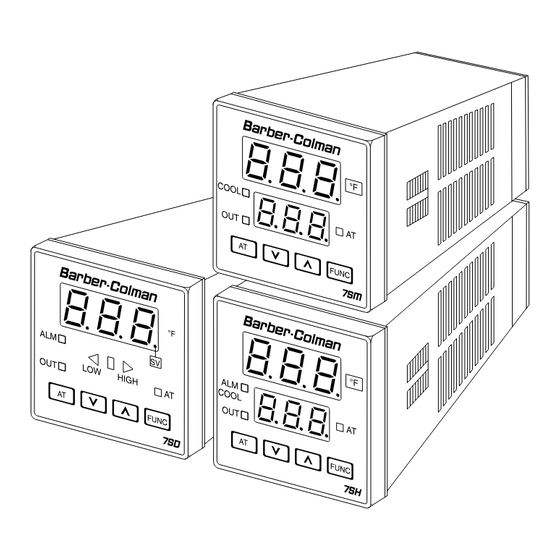
- Page 1 Instruction Manual 1262-IN-001-0-03 Models 7SD 7SH 7SM July 1998 Controllers...
- Page 2 1/16 DIN, THREE DIGIT DISPLAY TEMPERATURE CONTROLLER MODEL: 0 7 - 4 9 0 0 - 0 - 0 0 Field. 1 2 3 4 5 6 7 8 9 10 11 12 13 14 15 Fields 1 through 4. BASE Field 8.
- Page 3 CONGRATULATIONS Unpack the Instrument Congratulations on your purchase of one of the easiest to configure controllers on the market. After a four step configuration procedure, your process will be up and running. Wiring GUIDE TO SIMPLE SET-UP Only four steps are required to set-up your controller: Configuration 1.
- Page 4 Index 1/16 DIN, THREE DIGIT DISPLAY CAUTION: USE WIRE SUITABLE TEMPERATURE CONTROLLER ...... 2 FOR 75 °C MINIMUM MOUNTING REQUIREMENTS ......... 5 DIMENSIONS AND PANEL CUTOUT ....... 6 WIRING GUIDELINES ..........7 CONFIGURATION PROCEDURE ......12 Configuration Key Functions ......12 Configuration Procedure .........
-
Page 5: Mounting Requirements
Panel surface texture must be smoother than 6.3 µm. MOUNTING REQUIREMENTS To assure IP65 and NEMA 4X protection, insert the panel Select a mounting location with the following gasket between the instrument and the panel as shown characteristics: below. 1) Low vibration. 2) An ambient temperature range between 0 and 50 °C Install the instrument as follows: (32 and 122 °F). -
Page 6: Dimensions And Panel Cutout
DIMENSIONS AND PANEL CUTOUT 48 mm (1.890 in) 48 mm (1.890 in) 10 mm 122 mm 75 mm (0.394 in) (4.803 in) (2.953 in) 45 mm, -0, +0.6 mm (1.772 in, -0, +0.024 in) -
Page 7: Wiring Guidelines
Measuring inputs WIRING GUIDELINES Any external components (like zener diodes, etc.) connected between the sensor and input terminals may Terminal board cause measurement errors (excessive or unbalanced line resistance or possible leakage currents). TC input MAIN RELAY Shield Shield SAFETY NOTE: 1) Do not run input wires with power cables. - Page 8 RTD input SAFETY NOTE: 1) Do not run RTD wires with power cables. NOTES: 1) Ground shielded cable at one end only. 2) Use the correct size copper wires. 3) The resistance of the 3 wires must be the same. Any external components (like zener diodes, etc.) connected between the sensor and input terminals may cause measurement errors (excessive or unbalanced line...
- Page 9 Thermocouple compensating cable color codes. s i t l a i o l l o l l o l l o l l o l l o l l o l l l o i l o i / l i l i s...
-
Page 10: Safety Notes
B.1) Relay outputs B.2) Inductive loads High voltage transients can occur when switching inductive loads. It is recommended to install an additional RC network across the internal contacts as shown. The same problem can occur when a switch is used in series with the internal contacts. - Page 11 B.3) Voltage outputs for SSR drive 3) To avoid shock and possible instrument damage, This is a time proportioning output. connect power last. 4) Before connecting the power line, check that the Logic voltage for SSR drive. voltage is correct (see Model Number). Logic level 0: Less than 0.5 Vdc.
-
Page 12: Configuration Procedure
Configuration Procedure CONFIGURATION PROCEDURE 1) Switch off power to the instrument. Configuration Key Functions 2) Remove the instrument from its case. 3) Open switch V2, located 1 inch behind the upper right FUNC = The new setting of the selected parameter is corner of the display (see Figure 1). - Page 13 Input type and standard range Output 2 function 0 to +800 °C = TC type range 0 = None 0 to +800 °C = TC type range 1 = Process alarm 0 to +999 °C = TC type range 2 = Band alarm 0 to +999 °C = TC type range...
- Page 14 Safety lock Alarm action = Unlocked. All the parameters can be modified. Not available when P5 = 0 or 5. = Locked. Nothing can be modified except the SP. r = Reverse (relay de-energized in the alarm condition). 2 to 499 = This code number is a password used to unlock d = Direct (relay energized in the alarm condition).
- Page 15 Deviation bar graph resolution (3 digit deviation bar only) For an RTD input with a decimal place, P13 can be set from 0.2 to 20.0 °C. For all other inputs, it can be set from 2 to 200 engineering units. P13 is the band around the setpoint at which the deviation display changes (see graphic).
- Page 16 Advanced Configuration Procedure Automatic modification of “relative cooling gain” (3 digit dual display model) Enable/disable the display of the protected This parameter is present only when P5 = 5. parameters OFF = Autotuning does not modify the “relative Not available when P11 = 0. Enables/disables the display cooling gain.”...
-
Page 17: Operating Mode
Operating Key Functions OPERATING MODE FUNC = The new setting of the selected parameter 1) Remove the instrument from its case. is stored and the next parameter is 2) Close switch V2 (see Figure 1, Configuration Procedure). displayed (in increasing order). 3) The default setting for a sensor break indication is an = Starts and stops autotuning (press and hold overrange condition. - Page 18 Setpoint Access Displaying the Setpoint (3 digit deviation bar model) To change the setpoint, follow this procedure: 1) Press the key (and hold for 3 seconds); the To display the programmed setpoint, press the key. setpoint will start to change. The display will show the setpoint with the decimal point 2) Once the desired setting is reached, wait 3 seconds of the least significant digit flashing to indicate that the...
- Page 19 Operating Parameters Hysteresis (for ON/OFF control) Range: 0.1 to 10% of input span. From the “normal operating mode,” press the FUNC key. Integral time (from 1 minute and 20 seconds The lower display will show the code while the upper to 20 minutes and 0 seconds;...
- Page 20 Error Messages Error list EEPROM write error. Overrange or underrange indication CPU error. The instrument shows the OVERRANGE and Attempt to write to protected memory. UNDERRANGE conditions with the following indications: 201 - 2xx Configuration parameter error. The two least significant digits show the number of the wrong parameter (ex.
- Page 21 Default Parameters This indicates that the loading procedure has been initiated. After about 3 seconds the loading procedure is Loading default operating parameters complete and the instrument reverts to the “normal The control parameters can be loaded with display mode.” The following is a list of the default predetermined default values.
- Page 22 Default Configuration Parameters e) Within 10 seconds, press the key. The display will show: The configuration parameters can be loaded with predetermined default values. These are the settings loaded into the instrument prior to shipment from the factory. To load the default values proceed as follows: a) Open switch V2 (see Figure 1, Configuration Procedure).
- Page 23 Default configuration parameter list ° F ° ° F ° ° F ° ° 0 F ° ° 0 F ° ° 0 F ° ° F ° ° F ° ° F °...
-
Page 24: Specifications
Normal Mode Rejection Ratio: 60 dB @ 50/60 Hz. SPECIFICATIONS Operating Temperature: 0 to 50 °C. Storage Temperature: -20 to 70 °C. General Humidity: From 20 to 85% RH non-condensing. Case: Dark grey polycarbonate. Self-extinguishing Control Actions degree V-0 according to UL-94. Front Protection: Designed and tested for IP65 and On/Off, PID or autotuning (Smart AT) NEMA 4X for indoor locations (when panel gasket... - Page 25 Outputs 3 Digit Deviation Bar Characteristics Main Output Display: a) Relay SPDT, contact rating 3 Amps @ 250 Vac 3 digit 7 segment LED display; 10 mm high. on resistive load. Bargraph: b) Logic output for SSR, 700 Ω maximum load, 1 green LED + 2 red LEDs for 5 level deviation short circuit protected.
-
Page 26: Calibration Procedure
CALIBRATION PROCEDURE Calibration Parameters Following is a complete list of calibration symbols: Calibration parameters are logically divided into groups Code Parameter of two parameters each - minimum range value and TC Input Minimum Range Value maximum range value. A calibration check is provided TC Input Maximum Range Value after entering the values of each group. - Page 27 Entering Calibration Values TC input check The display will show ”t.” followed by a number showing TC input minimum range value the measured value in counts. The calibration for “tH” is correct if the indication is “t.30 000” ±10 counts. a) Connect calibrator and instrument as shown below.
- Page 28 Cold junction compensation RTD input minimum range value NOTE: Make sure tL and tH are correctly calibrated a) Connect a resistor box and the instrument as shown before attempting rJ calibration. below. a) Measure the temperature close to terminals 1 and 3 using an appropriate instrument, as shown below.
-
Page 29: Maintenance
RTD input check This completes the calibration procedure. To enter the The display shows “P.” followed by a number showing configuration procedure press the key, the display will the measured value in counts. The calibration for “PH” show “CnF”. If configuration and calibration are complete, is correct if the indication is “P.30 000”... - Page 30 Notes...
- Page 31 Notes...
- Page 32 Barber-Colman Company Industrial Instruments Division 1354 Clifford Avenue P.O. Box 2940 Loves Park, IL U.S.A. 61132-2940 Telephone +1 800 232 4343 Facsimile +1 815 637 5341 http://www.barber-colman.com A Siebe Group Company Copyright © 1997 Barber-Colman Company.
Need help?
Do you have a question about the Barber Colman 7SD and is the answer not in the manual?
Questions and answers
Why does my barber Coleman 7 s h controller keeping me a 305 error code yet I've entered the proper parameters. The right parameters parameter. I do notice that every time I go back to reinstall the right parameters parameter 11 each turning back to number two. Hope you can answer this ASAP be to the fact that we are down