
Summary of Contents for Range Video RVOSD Gen 5
- Page 1 RVOSD Gen 5 On Screen Display + Autopilot for Model Airplanes RangeVideo.com 14/JUL/2011...
-
Page 2: Table Of Contents
TABLE OF CONTENTS TABLE OF CONTENTS 5.6.1 Main menu, page 1/4 ....15 1 INTRODUCTION ......2 5.6.2 Main menu, page 2/4 ....16 5.6.3 Main menu, page 3/4 ....17 2 SAFETY PRECAUTIONS ..3 5.6.4 Main menu, page 4/4 ....19 5.6.5 Autopilot menu, page 1/3 .. - Page 3 TABLE OF CONTENTS 6.24 Configuring OSD Display ..36 8 UPDATING THE FIRMWARE .. 46 6.25 Configuring GPS ...... 37 6.25.1 GPS Satellite Lock ....37 9 SYSTEM SPECIFICATIONS & 6.26 Configuring Current Sensor ... 38 LIMITATIONS ......47 6.27 Debug Screen......38 9.1 RVOSD5 Specifications ...
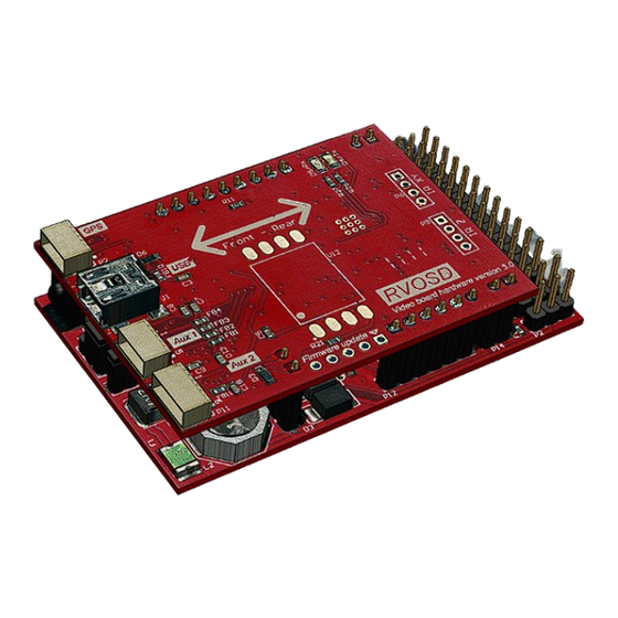
- Page 5 LIST OF FIGURES List of Figures Figure 3-1 Person Flying via FPV .................. 4 Figure 5-1 Autopilot Block Diagram ................6 Figure 5-2 RVOSD ......................7 Figure 5-3 GPS Receiver ....................8 Figure 5-4 Current Sensor ....................8 Figure 5-5 Remote Control ..................... 9 Figure 5-6 Video Camera .....................
-
Page 6: Introduction
This highly versatile, user-friendly system was designed with affordability and high performance in mind. Do keep in mind that the Range Video Screen Display Generation (RVOSD5) and your remote controlled aircraft have certain requirements and limitations. observing... -
Page 7: Safety Precautions
LIST OF FIGURES SAFETY PRECAUTIONS NOTE Definitions A procedure, practice, or condition, etc. that 2.1.1 Warnings, Cautions and Notes essential to emphasize. signal words WARNING, CAUTION, and NOTE are used to 2.1.2 Use of Shall, Should and May identify levels of hazard seriousness. Within this technical manual, the word These signal words are used throughout shall is used to indicate a mandatory... -
Page 8: About Rvosd5
RVOSD5 USER MANUAL ABOUT RVOSD5 What is FPV Flying? First Person Viewing (FPV) is an RVOSD: GPS, IR sensors, camera, exciting offshoot of a 60+ year old video transmitter, main flight battery, hobby, which enables a pilot of a radio- auxiliary battery, R/C receiver and flight controlled plane to immerse themselves control servos. - Page 9 SYSTEM DESCRIPTION|CHAPTER 2 KIT CONTENTS RVOSD5 Included Hardware (1) RVOSD5 with GPS RVOSD5 to handle common user errors (1) Current sensor with connecting cable like reverse battery connections and (1) Temperature sensor short circuits on the video in/out power (1) IR remote rails.
-
Page 10: System Description
RVOSD5 USER MANUAL SYSTEM DESCRIPTION Aircraft Compatibility RVOSD5 Overview The RVOSD autopilot can control these The RVOSD5 provides the pilot with types of aircraft: real-time navigation and aircraft system • Stable trainer aircraft. Throttle, information. information elevator, and rudder. superimposed over a video source and broadcast back down to the r/c pilot via a video transmitter/receiver system;... -
Page 11: Flight Modes
SYSTEM DESCRIPTION|CHAPTER 2 Flight Modes Component Overview RTH, (return This autopilot mode will 5.4.1 RVOSD5 home) engage automatically The RVOSD performs all of the text and when R/C link lost is detected, and will fly the graphic overlay, navigation, autopilot model back control, and power management. -
Page 12: Current Sensor
RVOSD5 USER MANUAL NOTE External Temperature Sensor GPS Ground Track, also The external temperature sensor can be known as GPS Heading is used to monitor engine, ESC, or battery not the same as Magnetic temperature. or True Heading. Ground track dependent aircraft flight directions and winds at altitude. -
Page 13: Wiring
SYSTEM DESCRIPTION|CHAPTER 2 NOTE If you lose the included remote, you can replace it with universal remote. Just program the universal remote for Sony TV codes. The “mute” key will change screens, Channel (+) and Channel (–) will change menu selection, volume (+) and volume (-) will change the menu value. -
Page 14: Video Transmitter
RVOSD5 USER MANUAL that operates on the same frequency as your video transmitter. The video receiver will receive the transmitted video with RVOSD5 overlays. Connect the video receiver output to a video monitor to watch the video in real-time. 5.5.6 Video Monitor You will need a video monitor (not included with RVOSD5) to view the Figure 5-9 Video Camera... -
Page 15: Main Battery
SYSTEM DESCRIPTION|CHAPTER 2 5.5.7 Main Battery CAUTION Your electric aircraft already has a Double check all wiring and battery power motor hardware connections electronics. The RVOSD5 and related proper placement prior to components this existing connecting power battery as a power source. The Main source. - Page 16 RVOSD5 USER MANUAL • Video Input – supplies 5VDC or • OUT3/Throttle Output – Supplies 12VDC from the Main Battery to power and commands to the the video camera if the Main throttle servo. If you have battery is enabled by the jumper multiple throttle servos you will on the RVOSD5.
-
Page 17: Figure 5-12 Rcosd Main Board Pin-Outs
SYSTEM DESCRIPTION|CHAPTER 2 • Temperature Sensor/RSSI – This • Voltage Selection Jumpers - The where supplied RVOSD has a 5V 1.5A switch temperature sensor is connected mode regulator, which can be (optional). used to supply 5V to cameras and transmitters, and a filter for •... -
Page 18: Figure 5-13 Rvosd Interconnection Diagram
RVOSD5 USER MANUAL R/C receiver RSSI Throttle, rudder//aileron, elevator, aux control Video input camera Main battery can bypass the current sensor Video out video transmitter Main flight Current battery sensor RVOSD Aux battery Temp // RSSI IR X-Y sensor IR Z sensor Throttle, rudder//aileron, elevator servos/ESC... -
Page 19: Menu Description
SYSTEM DESCRIPTION|CHAPTER 2 output Signal Aileron in Servo pulse input 1.0-2.0mS 3-5VDC Signal Connect to your Elevator in Servo pulse input 1.0-2.0mS 3-5VDC receiver elevator output Signal Switch OSD screens Aux in Servo pulse input 1.0-2.0mS 3-5VDC in-flight Signal pin Temp in Analog voltage input Can be used for RSSI... -
Page 20: Main Menu
RVOSD5 USER MANUAL Figure 5-17 Low Altitude Angle *Disabled: Vario not shown Dist warning - Distance indicator will start *Digital: Vario display on digital form for the to blink when it goes over the value set on F16 screen this menu. *Analog: Vario display on analog form for Battery voltage warning - The Main the F16 and simple screens. -
Page 21: Main Menu
SYSTEM DESCRIPTION|CHAPTER 2 Set max HDOP - This value sets the Landing gear - Assign a channel of the minimum GPS signal Horizontal Dilution of PPM string to the OSD “Gear” input and you Position (HDOP) your OSD will accept to can configure the display to show when the landing gear is down. - Page 22 RVOSD5 USER MANUAL If the Rx input type menu item is selected RSSI level and second value shows the to Combined PPM there is additional actual RSSI level. options for the RSSI input. Maximum RSSI - With the R/C transmitter *Packet1: aileron input...
-
Page 23: Main Menu
SYSTEM DESCRIPTION|CHAPTER 2 R/C link lost detection - Selects the way navigation (USA-Canada). If the model reaches this distance from home R/C link lost is detected waypoints will be cancelled and the model *Glitch counter: Will check the auxiliary will go back to home. channel, if the incoming servo pulses have Display waypoint indicator - Enable or wrong pulse width or period, then R/C link is... -
Page 24: Autopilot Menu
RVOSD5 USER MANUAL *Test in the air: *Airplane: All outputs will match the board labels. *Test on the ground: -Elevator output --> Elevator Save configuration - -Saves all settings to -Aileron output --> Aileron permanent memory so when you cycle power to the OSD its parameters will be -Throttle output -->... -
Page 25: Autopilot Menu
SYSTEM DESCRIPTION|CHAPTER 2 • Fly by wire source selected “thermopiles” it is better to set this in flight. • Waypoint sequencer If the AHI source is selected to “IMU” is Main screen selection - Choose the main better to select this on the ground, or in flight screen;... -
Page 26: Autopilot Menu
RVOSD5 USER MANUAL If the AHI source is set to IMU. This menu separated tests of the rudder and elevator will set the board roll orientation. Allows the control to adjust the autopilot. OSD board placement, to be set at different Start IR sensors equalization - If the XY roll angles on the airframe. - Page 27 SYSTEM DESCRIPTION|CHAPTER 2 When the AHI source is set to Thermopiles angle when the plane is going completely away from home (maximum autopilot or IMU, this parameter will make the same output) action on the correction of the heading When the AHI source is set to Thermopiles changes (smoother changes of heading).
-
Page 28: On Screen Display
RVOSD5 USER MANUAL • Home Position Altitude integral gain - When the AHI source is set to None, this option adjusts • GPS Signal the gain of the rudder to elevator mix available if you want to compensate pitch • HDOP down due to rudder action. - Page 29 SYSTEM DESCRIPTION|CHAPTER 2 Figure 5-18 On Screen Display Description RangeVideo.com...
- Page 30 RVOSD5 USER MANUAL Figure 5-19 On Screen Display Description RangeVideo.com...
-
Page 31: Rvosd5 Configuration
SYSTEM DESCRIPTION|CHAPTER 2 RVOSD5 CONFIGURATION are using a PPM receiver in your Basic Configuration aircraft, this connection will also serve to detect link loss (R/C glitch NOTE detection). Please read carefully. The PCM Link Loss Detection autopilot configuration In PCM mode, the RVOSD detects R/C requires special attention. -
Page 32: Using Ppm Receivers
RVOSD5 USER MANUAL NOTE connection, please note the polarity of the connections. Infrared Thermopile Sensors are not used with the RVOSD5. An onboard IMU is used to perform the autopilot functionality. Using PPM Receivers In case you are using a PPM R/C Figure 6-1 Video TX Connector receiver which has no failsafes and NOTE... -
Page 33: Using An Auxiliary Battery For
SYSTEM DESCRIPTION|CHAPTER 2 the 2S-6S range. The RVOSD is do so, remove the Main battery shipped pre-configured for 12V to be enable/disable jumper to disable the supplied directly from the Main Battery Main bat from powering the camera and to the Video Input (camera) and Video transmitter when either 12V jumper is Output (transmitter) connections. -
Page 34: Connecting The Main Battery
RVOSD5 USER MANUAL remove the main bat enable The current sensor connects to RVOSD Main bat in/current sense port. jumper, and connect a 12V battery to Aux bat in. NOTE It is wise to check the voltage and polarity being supplied to your camera/transmitter before connecting them. -
Page 35: Aux Battery Input
SYSTEM DESCRIPTION|CHAPTER 2 values and the current reading will be See the autopilot section for more inaccurate- usually too high. details. If you connect two batteries: a 3s 11.1V Main flight pack and a 3s 11.1V Aux bat, and connect the main bat enable jumper, the RVOSD will use the the higher voltage battery. -
Page 36: Receiver Signal Strength Indication (Rssi)
RVOSD5 USER MANUAL CAUTION input channel changes autopilot modes. If you are FPV flying, this won’t be problem, but please pay attention if you are flying in third person mode accidentally activate autopilot mode. You will have to think and react fast! Consider disabling autopilot modes while... -
Page 37: Throttle Control
SYSTEM DESCRIPTION|CHAPTER 2 6.16 Throttle Control: menu, press until you see the Throttle control on the autopilot it’s fixed to two values, when the model is above main menu screen. “altitude limit”+”cruise altitude” buttons to scroll menu options. There throttle control is fixed to the value on are 4 pages in the main menu. -
Page 38: Changing Osd Screens
RVOSD5 USER MANUAL and aileron sticks. In order to allow This wizard will guide you step by step, these actions, the servo outputs will stay and set the following menu options for at the values they had just before you: entering the submenu. -
Page 39: If R/C Link Is Lost
SYSTEM DESCRIPTION|CHAPTER 2 NOTE These settings are located on main menu page 2/4. Rx not detected’ can also be displayed on startup if 6.21 Configuring Waypoints your throttle stick position RVOSD can be set to navigate thru up is higher than throttle FS to fifteen 3D waypoints. -
Page 40: Configuring Rssi Measurement36
RVOSD5 USER MANUAL Waypoint sequencer seen shown in a value from 0 to 100% that working from time 7:51 on this video: will match the signal received. If analog http://vimeo.com/19550368 display it’s selected it will take place of the Satellite bars indicator showing 10 RVOSD allows inputting... -
Page 41: Configuring Gps
SYSTEM DESCRIPTION|CHAPTER 2 can be found in Autopilot submenu page 1/3. 6.23 Configuring GPS Be sure that the GPS fix update: is set to 10Hz (default), if you are using the included 10Hz GPS module. Figure 6-8 Installing a Diode for RSSI RVOSD will display "Searching Sats"... -
Page 42: Configuring Current Sensor
RVOSD5 USER MANUAL Sequential satellite locks are called 6.25 Debug Screen warm starts. When the menu item “Debug screen” it’s set During a Warm Start the approximate to enable. The screen that is usually blank time to get satellite lock is: useful information. -
Page 43: Saving Osd Settings
SYSTEM DESCRIPTION|CHAPTER 2 6.26 Saving OSD Settings Make sure the “airplane type” is back to “Flying wing”. Remove the propeller! Changes will be lost on a power reset or OSD reset, unless you Save configuration. And run the “Start R/C wizard” menu item on, main menu page 1/4. - Page 44 RVOSD5 USER MANUAL • Altitude derivative gain done with the menu items “Stabilization pitch gain” and “Stabilization roll gain”. If • Altitude integral gain the plane attitude control is weak, the autopilot attitude corrections will be slow Some models, will not correct heading and you should increase the values for fast enough by just banking, for those the appropriate axis.
-
Page 45: Stuff You Need To Know
SYSTEM DESCRIPTION|CHAPTER 2 • Make sure the OSD does detect 6.29 Stuff You Need to Know! • Do not move the airplane during R/C link lost failure before taking OFF. Also you can test the the first 30 seconds after turning autopilot by triggering Level flight ON the power or a restart of the mode. -
Page 46: Setup Procedure
CHAPTER 4|SYSTEM LIMITATIONS SETUP PROCEDURE information does include a vibration Basic Setup level indicator for every axis. The The following steps will guide you through the common steps to install the RVOSD in goal is to keep the bar indicators your aircraft and prepare it for its first flight. - Page 47 SYSTEM LIMITATIONS|CHAPTER 4 NOTE Rx Rudder output ----> OSD rudder input/output ----> Rudder servo The inertial unit will be initializing. Keep RVOSD For flying wing: board quiet during the first 30 seconds after power The OSD will perform the elevon mixing.
-
Page 48: Ppm Receiver Setup
CHAPTER 4|SYSTEM LIMITATIONS Rx Aileron1 output ----> OSD aileron 12- Set OSD fail-safe’s on the menu item input/output ----> Aileron1 servo Set failsafe. Rx Throttle output ----> OSD throttle 13- Menu item Enable autopilot to Yes- input/output ----> ESC Aileron2 ---->... -
Page 49: Secondary Ppm Receiver
SYSTEM LIMITATIONS|CHAPTER 4 After all is done exit the menu. detected on either PPM1 or PPM2 inputs. The F16 screen will display the 7.2.2 Secondary PPM Receiver receiver input selected every Connect the second PPM receiver to the moment. throttle input channel of the OSD. The second PPM input should be Repeat configuration... -
Page 50: Updating The Firmware
CHAPTER 4|SYSTEM LIMITATIONS 8 UPDATING THE FIRMWARE RangeVideo.com... -
Page 51: System Specifications & Limitations
SYSTEM LIMITATIONS|CHAPTER 4 SYSTEM SPECIFICATIONS & LIMITATIONS RVOSD5 Specifications Performance Autopilot Limitations Weather Limitations 9.4.1 Temperatures RangeVideo.com... -
Page 52: Appendix A: List Of Acronyms
10 APPENDIX A: LIST OF ACRONYMS ....Artificial Horizon Indicator OSD ......On Screen Display ....... Center of Gravity ..........Channel RVOSD5 ....... Range Video OSD ........Radio Control FPV ......First Person View RPM ......Rotations per Minute GCS ..... Ground Control Station RSSI .. -
Page 53: Appendix B: Rvosd5 Jumper Settings
LIST OF ACRONYMS|APPENDIX E APPENDIX B: RVOSD5 JUMPER SETTINGS Main Batter = Enabled Camera = 12V Video TX = 12V Main Batter = Disabled Camera = 12V Video TX = 12V Main Batter = Enabled Camera = 5V Video TX = 12V Main Batter = Enabled Camera = 12V Video TX = 5V...
Need help?
Do you have a question about the RVOSD Gen 5 and is the answer not in the manual?
Questions and answers