Table of Contents
Advertisement
Operation and Installation Guide
In‐Car Video Link for
Copyright © 2014‐2016, Digital Ally, Inc. All Rights Reserved. This publication may not be reproduced, stored in a retrieval
system, or transmitted in whole or part in any form or by any means electronic, mechanical, recording, photocopying, or in any
other manner without the prior written approval of Digital Ally, Inc.
860‐00198‐00 Rev E
Advertisement
Table of Contents

Related Manuals for Digital-Ally VuLink

Summary of Contents for Digital-Ally VuLink
- Page 1 860‐00198‐00 Rev E Operation and Installation Guide In‐Car Video Link for Copyright © 2014‐2016, Digital Ally, Inc. All Rights Reserved. This publication may not be reproduced, stored in a retrieval system, or transmitted in whole or part in any form or by any means electronic, mechanical, recording, photocopying, or in any other manner without the prior written approval of Digital Ally, Inc. ...
-
Page 2: Table Of Contents
HD ..............4-1 SING AULT TO ONFIGURE YOUR INK AND IRST Configuring VuLink ............................4-2 Activating VuLink ............................4-3 Assigning Your FirstVu HD to a VuLink Device ...................4-4 Activating FirstVu HD within VuVault ......................4-5 HD .........4-5 SING ONFIGURATION ANAGER TO ONFIGURE YOUR INK AND IRST Installing the Software ..........................4-6 ... -
Page 3: Section - 1: Before You Begin
‘slack’ in the cable connections to allow for service loops so the connections do not get pulled or accidentally disconnected. We recommend at least 2 feet of distance between VuLink and that of other systems which may carry a signal for transmit and/or receive. - Page 4 VuLink Operation & Installation Guide 860‐00198‐00 REV E Digital Ally, Inc. | Before you Begin 1‐2 ...
-
Page 5: Section - 2: Installation Instructions
Step 1: Prepare the vehicle 1. VuLink is typically mounted on the windshield near the roofline area. Plan a safe path for the base cable from the windshield area to your power source and remove necessary body trim pieces. Remove front passenger side threshold. -
Page 6: Step 2: Power, Ignition, And Ground Connections
IF box output alarm. The wire is the VuLink output trigger. When you press the record button on your FirstVu HD, VuLink will apply a 1 second +12VDC signal on this wire. Make the connections as shown in the table below:... -
Page 7: Step 4: Vulink Installation
860‐00198‐00 REV E Step 4: VuLink Installation Plug the base cable into the connector on the side of VuLink. Prep the windshield glass with alcohol to remove any dirt or debris. Using the included Velcro kit, attach VuLink to an unobstructed location on the windshield below the roofline. -
Page 8: Section - 3: Model-Specific Wiring Diagrams
The DVM‐100/400 models do not have an output alarm sensor. Therefore, VuLink cannot trigger the FirstVu HD to automatically record if the RECORD BUTTON is pressed on the front of the DVM, or if the WIRELESS MICROPHONE is used to initiate a recorded event. -
Page 9: Dvm-500Plus / Dvm-750
I/F Box The DVM 500plus/750 models do not have an output alarm sensor. Therefore, VuLink cannot trigger the FirstVu HD to automatically record if the RECORD BUTTON is pressed on the front of the DVM, or if the WIRELESS MICROPHONE is used to initiate a recorded event. -
Page 10: Dvm-800 / Dvm-Live
VuLink Operation & Installation Guide 860‐00198‐00 REV E DVM-800 / DVM-LiVE DVM‐800 Wireless Microphone VuLink Base Cable ... -
Page 11: Dv-440Ultra
The DV‐440Ultra does not have an output alarm sensor. Therefore, VuLink cannot trigger the FirstVu HD to automatically record if the RECORD BUTTON is pressed on the front of the unit, or if the WIRELESS MICROPHONE is used to initiate a recorded event. -
Page 12: Dvm-250Plus Or Dvm250 (With Interface Box)
VuLink Operation & Installation Guide 860‐00198‐00 REV E DVM-250Plus or DVM250 (with interface box) VuLink Base Cable ... -
Page 13: Microvu Hd
860‐00198‐00 REV E MicroVu HD When using VuLink with a MicroVu HD, the VuLink is only wired to the Vehicle Power, Ground, and Ignition. The MicroVu HD provides all event triggers to VuLink based on its own sensor input connections. Triggering between the MicroVu HD and the FirstVu HD is provided through wireless communication with VuLink. -
Page 14: Generic Input Source
Using this method, an in-car video system is not required. Your FirstVu HD may be wirelessly activated by connecting VuLink to any vehicle input sensor. Use the Orange wire if connecting to the emergency lights or other +12VDC trigger. Or, use the Brown wire if connecting to an active low (0VDC) input trigger. -
Page 15: Section - 4: Vulink Configuration
You must have VuVault version 4.5 or above to configure and activate a VuLink device. MicroVu HD requires VuVault 4.7 or above. VideoManagerII and previous versions of VuVault will not work with VuLink. Log on to http://www.digitalallyinc.com/login.cfm... -
Page 16: Configuring Vulink
860‐00198‐00 REV E Configuring VuLink VuLink is a secured 802.11n 2.4GHz wireless access point which your FirstVu HD’s will use to communicate with your in-car video system and/or auxiliary sensors (such as lights, siren, etc.). The wireless configuration parameters are located in the Admin>Devices>VuLink Settings tab. -
Page 17: Activating Vulink
1. If configured to 0 minutes; the Ignition Shutdown Timer is disabled, and VuLink will shut down when ignition is turned off. 2. If the FirstVu HD is not recording, all LED Indicators will turn off, but VuLink will remain fully powered until the timer expires. -
Page 18: Assigning Your Firstvu Hd To A Vulink Device
Method B: Unique VuLink Setting Method (preferred method) In most cases, you will want to assign each FirstVu HD in your fleet to a different VuLink device. Using this method, unintentional triggers will not occur if two fleet vehicles are in close proximity to each other. -
Page 19: Activating Firstvu Hd Within Vuvault
VuVault, follow the instructions in this section to configure and activate your device using the stand-alone Mini Configuration Manager software. Using this method, you will assign all of your FirstVu HD’s to a single VuLink by creating a configuration file. To set up multiple VuLink configurations, repeat the following process for each VuLink device and save the new configuration file to VuLink and associated FirstVu HD’s. -
Page 20: Installing The Software
Configuring VuLink Open the Mini Configuration Manager. Press the Add button to display the list of available options for VuLink, and press the Add button next to FirstVu HD. Select the Vulink tab. VuLink is a secured 802.11n, 2.4GHz wireless access point which your FirstVu HD’s will use to communicate with your in-car video system and/or auxiliary sensors... - Page 21 7. If configured to 0 minutes; the Ignition Shutdown Timer is disabled, and VuLink will shut down when ignition is turned off. 8. If the FirstVu HD is not recording, all LED Indicators will turn off, but VuLink will remain fully powered until the timer expires.
-
Page 22: Saving Your Settings
FirstVu HD settings, consult the FirstVu HD Operation Guide. To complete the activation, you must write the configuration file named “deviceconfig” to your FirstVu HD and Vulink devices. Once the file is written, the devices can communicate wirelessly. Saving your FirstVu HD settings 1. -
Page 23: Dvm-800, Dvm-250, And Dvm-250Plus Device Configuration
If you have a Digital Ally DVM-800, or DVM-250 series video system, you must assign the VuLink output trigger to an IF box input sensor. Using this configuration, the FirstVu HD will be enabled to trigger device recordings and have a customized trigger name. From your VuVault or Configuration Manager Settings tab, enable the desired sensor to be used with VuLink. -
Page 24: Section - 5: Operation
7. Start a recorded event by activating your emergency lights. 8. The Red status indicator on VuLink will turn on to indicate the event is being recorded. The Red status indicator on the FirstVu HD and ICV should also turn on indicating that they are also recording. -
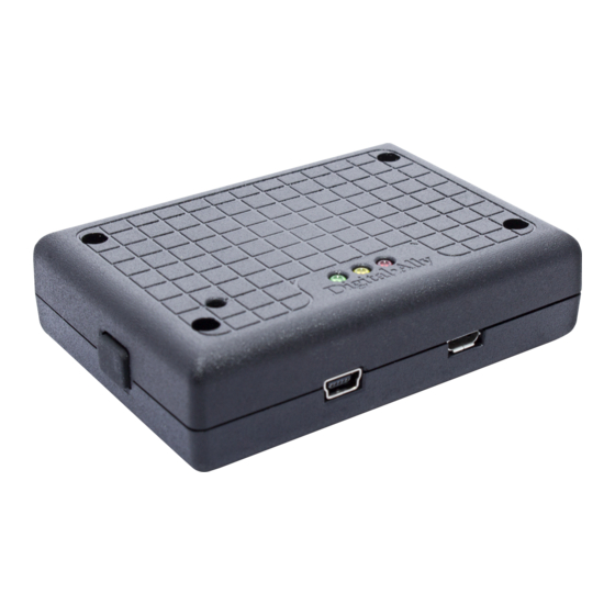
Page 25: U Link ™ Led Status Indicators
Upgrade FirstVu HD™ LED Status Indicator The FirstVu HD yellow status LED will be illuminated whenever a wireless link is established with VuLink. For a complete list of status indicators, consult the FirstVu HD Operation Guide. GREEN YELLOW ... -
Page 26: Section - 6: Support
The file name is: firmware.r 5. Right-click on the VuLink drive and select Eject, then disconnect the USB cable from the device. The Green LED indicator should be on and the Yellow and Red indicators will alternately flash while the new firmware is being installed. Wait for this operation to complete. -
Page 27: Troubleshooting
FirstVu HD battery may be low. Replace FirstVu HD battery. Product Repair VuLink should be returned to Digital Ally for service. The warranty may be voided if the device is opened by any unauthorized individual. Please contact Digital Ally to obtain a Return Materials Authorization (RMA). -
Page 28: Section - 7: Warranty Information
860‐00198‐00 REV E Section ‐ 7: Warranty Information We warranty that VuLink™ will be free from defects in workmanship and material for a period of 12 months from the date of purchase by the original purchaser. If any defect is discovered through normal and proper use of the unit during this period, the defect will be repaired or the unit will be replaced at our factory or at one of our authorized service centers at no cost to the purchaser. -
Page 29: Section - 8: Contact Information
VuLink Operation & Installation Guide 860‐00198‐00 REV E Section ‐ 8: Contact Information 9705 Loiret Blvd Lenexa, KS 66219 Website: www.digitalallyinc.com Support E-Mail: support@digitalallyinc.com Sales E-Mail: sales@digitalallyinc.com Phone: 913-814-7774 Fax: 913-814-7775 Sales / Support Toll Free: 1-800-440-4947 ... -
Page 30: Section - 9: Regulatory
Reorient or relocate the receiving antenna. Increase the separation between the user equipment and VuLink. Connect the user equipment into an outlet on a circuit different from that to which VuLink is connected. Contact Digital Ally technical support.
Need help?
Do you have a question about the VuLink and is the answer not in the manual?
Questions and answers