Advertisement
Quick Links
To ensure a timely delivery, please include the following:
1. Full Name
2. Physical Address (Our primary carrier, FedEx, will NOT deliver to P.O. Boxes)
3. Phone Number
4. QC Number : GV
5. ZLN Number : ZL7227-58M29U_V00
6. Part Number(S) or Letter (S)
7. Quantity
8. We also request that you please provide a brief description of the reason for your request.
Advertisement

Summary of Contents for Z-Line Designs Merako ZL7227-58M29U
- Page 1 To ensure a timely delivery, please include the following: 1. Full Name 2. Physical Address (Our primary carrier, FedEx, will NOT deliver to P.O. Boxes) 3. Phone Number 4. QC Number : GV 5. ZLN Number : ZL7227-58M29U_V00 6. Part Number(S) or Letter (S) 7.
- Page 15 NOTE: Refer to the Hinge Adjustment Supplement (next page) for more information.
- Page 16 HINGE ADJUSTMENT SUPPLEMENT...
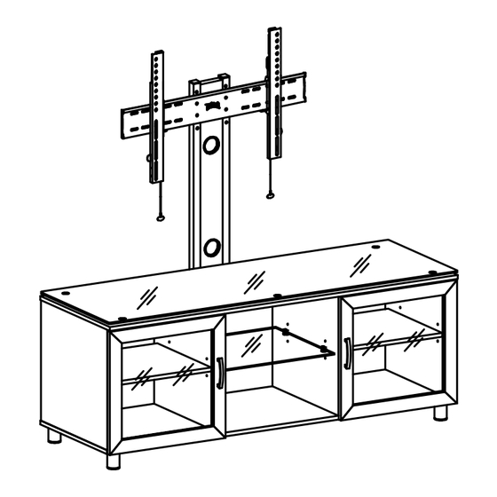
- Page 17 OPTION 1: If you want your Flat Panel TV to sit on the top shelf of the unit, congratulations your Z-Line Designs Merako TV Stand is almost complete! OPTION 2: If you want your Flat Panel TV to be mounted to the integrated long back panel with mount featuring, please continue on to Steps 11 and 23-25.
- Page 19 STEP 12 (OPTION 3 ASSEMBLY ONLY) - Wood Stud Mounting: Using a Stud Finder, locate the Studs you will be mounting (17) Upper Mounting Panel to (in Step 19) and mark the CENTER locations. Use a Level to draw a Vertical Line along the CENTER of each Wall Stud at least 8" (Eight Inches) long at your desired height.
- Page 20 1. Fold the Middle Flaps located on (22) Mounting Template Guide INWARD (AWAY from the wall) and remove the Adhesive Covers. 2. With the Middle Flaps still folded inward, position (22) Mounting Template Guide over the Vertical Lines (drawn in Step 13) so that the lines can be seen through the Slots located at the Top and Bottom of the Template. 3.
- Page 21 THE SPACE BETWEEN (MQ) LAG BOLTS MUST BE AT LEAST 16" APART. 1. Make sure your Mounting Surface is free of dust and debris. 2. Fold the Middle Flaps located on (22) Mounting Template Guide INWARD (AWAY from the wall) and remove the Adhesive Covers.
- Page 23 1. Measure the distance from 2" to 3" ABOVE the BOTTOM of your Plasma/Flat Panel TV to the desired location (Outlet or Media Stand) and mark that length on the Cable Cover, using a straight edge. 2. Now carefully cut the (20) Cable Cover Back Plate and (21) Cable Cover Front Plate with a Fine Tooth Saw. 3.
- Page 27 STEP 24A (Flat Back TV) 1. Please use the 15mm long Machine Screws (MD, MF, MH and MJ). 2. Now insert (MD) or (MF) through the Small holes located on (MA) Dual Hole Washers or insert (MH) or (MJ) through the Large holes located on (MA) Dual Hole Washers, next through (18/19) Mounting Rails, and then into the TV.
- Page 28 STEP 24B (Rounded, Inset or Obstructed Back TV)
- Page 29 ZL7227-58M29U--Page 29 of 35...
- Page 30 NOTE: THIS IS AN INFORMATIONAL FIGURE ON THE OPERATION OF 18/19 LEFT/RIGHT MOUNTING RAILS. PLEASE READ BEFORE ATTEMPTING TO MOUNT YOUR PLASMA/FLAT PANEL TV.
- Page 31 NOTE: THIS IS AN INFORMATIONAL FIGURE ON THE OPERATION OF 18/19 LEFT/RIGHT MOUNTING RAILS. PLEASE READ BEFORE ATTEMPTING TO MOUNT YOUR PLASMA/FLAT PANEL TV. NOTE: THIS IS AN INFORMATIONAL FIGURE ON THE OPERATION OF 18/19 LEFT/RIGHT MOUNTING RAILS. PLEASE READ BEFORE ATTEMPTING TO MOUNT YOUR PLASMA/FLAT PANEL TV. ZL7227-58M29U--Page 31 of 35...
- Page 33 USB HUB & WIRE MANAGEMENT COVER INSTALLATION ZL7227-58M29U--Page 33 of 35...
- Page 35 Product size:58"(W ) x 21-1/4"(D) x 57"(H ) 65 Lbs. ZL7227-58M29U--Page 35 of 35...
- Page 37 Follow Z-Line Designs on all of your favorite social networks zlinedesigns zlinedesigns Or online at www.z-linedesigns.com...
- Page 40 ZL7227-58M29U_V00_GV...
Need help?
Do you have a question about the Merako ZL7227-58M29U and is the answer not in the manual?
Questions and answers