Table of Contents
Advertisement
Advertisement
Table of Contents

Summary of Contents for Giada DE67
- Page 1 - 1 -...
- Page 2 Statement The copyright of this manual belongs to Shenzhen JEHE Technology Development Co., Ltd. (Giada, JEHE’s global brand) and all rights are reserved. The company reserves the right to change this manual at any time without notification. Specifications here are for reference only, please take the real product as standard.
-
Page 3: Table Of Contents
Table of Contents 1. Product Introduction ....................5 2. Interface Description and Hardware Specifications ..........5 2.1 Interface Description .................... 5 2.2 Hardware Specifications ..................6 3. Accessories Installation Steps ................. 7 3.1 Memory Installation ..................... 8 3.2 WiFi/3G/4G Installation ..................9 3.3 MSATA Installation .................... - Page 4 4.2.7 CSM Configuration ................... 27 4.3 Chipset ........................ 29 4.4 Security Setup ....................31 4.5 Boot Menu ......................32 4.6 Save & Exit ......................34 5. JAHC Introduction ....................35 5.1 Auto Power On ....................35 5.2 JAHC Software ....................35 5.2.1 JAHC Software Functions ................
-
Page 5: Product Introduction
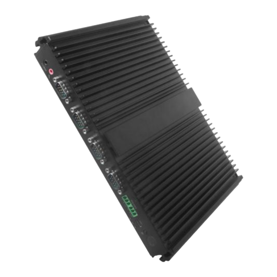
1. Product Introduction Based on Kabylake platform, Giada DE67 adopts high performance Intel® core processors. Configured with rich I/O ports, the player is suitable to be applied in high-end digital signage, kiosk and automation control applications. 2. Interface Description and Hardware Specifications 2.1 Interface Description... -
Page 6: Hardware Specifications
2.2 Hardware Specifications DE67 Intel ® Core™ i3-7100U Intel ® Core™ i5-7200U Processor Frequency 2.4 GHz 2.5 GHz up to 3.1 GHz BIOS AMI Source Code Chipset Type DDR3L – 1600MHz Memory Socket 2 x SO-DIMM Max Capacity 32 GB Intel ®... -
Page 7: Accessories Installation Steps
Operating 0-40℃ at 0.7m/s Air Flow Environment Temperature Relative Humidity 95%@40℃ (non-condensing) Certification CE, FCC Class B 3. Accessories Installation Steps For safety reasons, please ensure that the power cord is disconnected before opening the case. How to open the cover Unscrew the two screws and remove the top cover. -
Page 8: Memory Installation
3.1 Memory Installation This product only supports DDR3L SO-DIMM memory modules. 1. Locate the SO-DIMM slot on the board. 2. Gently insert the module into the slot in a 45-degree angle. 3. Carefully push down the memory module until it snaps into the locking mechanism. - 8 -... -
Page 9: Wifi/3G/4G Installation
3.2 WiFi/3G/4G Installation WIFI Installation 1. Tighten the WIFI module and WIFI module bracket with screws. 2. Plug the WIFI module into the mini PCIE slot. 3. Secure the module to the carrier by tightening up the screw. 4. Connect two black cables to Main and AUX. Install the antennas. ... -
Page 10: Msata Installation
3.3 MSATA Installation 1. Plug the MSATA module into the mini PCIE slot. 2. Secure the module to the carrier by tightening up the screw. 3.4 SSD (M.2) Installation 1. Plug the SSD (M.2) into the appropriate slot. 2. Secure the module to the carrier by tightening up the screw. - 10 -... -
Page 11: Sata Installation
3.5 2.5’’SATA Installation 1. Unscrew the two screws from the carrier. 2. Tighten up the two screws on the back side of 2.5'' SATA disk. 3. Plug 2.5''SATA disk into the slot and tighten up the two screws on front side to fix it 4. -
Page 12: Sim Card Installation
3.6 SIM Card Installation This product supports standard SIM card with the size of 25mm × 15mm. 1. [Open] the SIM card holder and pull it up. 2. Insert the SIM card. 3. [Lock] the card holder. - 12 -... -
Page 13: Bios Setup
The descriptions relating to BIOS setup in this Manual is for reference only since the BIOS version of the product might be upgraded. Giada provides no guarantee that all the contents in this Manual are consistent with the information you acquired. - Page 14 B. Function Keys definitions Hot Key Description ↑ (Up key) Move to the previous item ↓ (Down key) Move to the next item ← (Left key) Move to the left item → (Right key) Move to the right item Exit the current interface Page Up Change the setup state, or add the values Page Down...
- Page 15 Fig 1 1) Main (standard CMOS setup) This item is used for setting the date and time. 2) Advanced (advanced BIOS setup) This item is used for setting the advanced functions provided by BIOS, such as specifications of PCIe facilities, CPU, HDD, etc.
-
Page 16: Main (Standard Cmos Setup)
4.1 Main (Standard CMOS Setup) 1) System time (hh:mm:ss) Use this item to set the time for the computer, with the format as “HH / MM / SS”. 2) System date (mm:dd:yy) Use this item to set the date for the computer, with the format as “week, MM / DD / YY”. - 16 -... -
Page 17: Advanced (Advanced Bios Setup)
4.2 Advanced (Advanced BIOS Setup) 4.2.1 CPU Configuration - 17 -... -
Page 18: Acpi Settings
CPU Configuration Menu Description SW Guard Extensions (SGX) Enable/Disable Software Guard Extensions (SGX). There are three Owner EPOCH modes (Each EPOCH is 64bit). No change in owner epoch change to new random owner epoch Select Owner Epner EPOCH input type ... - Page 19 ACPI Menu Description Enable ACPI Auto Configuration Enables or Disable BIOS ACPI. Enable Hibernation This item may not be effective with some operating system. Select the highest ACPI sleep state, the system will enter when ACPI Sleep State the SUSPEND button is pressed. Lock legacy Resources Enable/Disable Lock of Legacy Resources.
-
Page 20: Lan Configuration
4.2.3 LAN Configuration LAN Configuration Menu Description I211 Onboard LAN Control Enable/Disable Onboard LAN Control. 219LM LAN Controller Enable/Disable Onboard LAN Control. - 20 -... -
Page 21: Super Io Configuration
4.2.4 Super IO Configuration Super IO Configuration Description This item can be used to set the Serial Port 1 after entering the Serial Port 1 Configuration Serial Port 1 Configuration. It can be set according to user's needs. This item can be used to set the Serial Port 2 after entering the Serial Port 2 Configuration Serial Port 2 Configuration. - Page 22 Super IO Configuration Description Serial Port 1 Configuration The serial port is enabled by default. Serial Port Enabled Disabled. User can set the serial port by change settings option. Auto IO=3F8H ; IRQ=4 ; IO=3F8H ; IRQ=3 , 4 , 5 , 6 , 7 , 9 , 10 , 11 , 12 ; ...
- Page 23 Super IO Configuration Description Serial Port 3 Configuration The serial port is enabled by default. Serial Port Enabled Disabled. Device Settings IO-3E8h; IRQ=7; User can set the serial port by change settings option. Auto IO=3E8H ; IRQ=4 ; ...
- Page 24 Super IO Configuration Description IO=2F8H ; IRQ=3 , 4 , 5 , 6 , 7 , 9 , 10 , 11 , 12 ; IO=3E8H ; IRQ=3 , 4 , 5 , 6 , 7 , 9 , 10 , 11 , 12 ; ...
- Page 25 Super IO Configuration Description Serial Port 6 Configuration The serial port is enabled by default. Serial Port Enabled Disabled. Device Settings IO-2E0h; IRQ=7; User can set the serial port by change settings option. Auto IO=3F8H ; IRQ=4 ; ...
-
Page 26: Hardware Monitor
4.2.5 Hardware Monitor 4.2.6 Wake Configuration - 26 -... -
Page 27: Csm Configuration
Options Description Wake Configuration The user can set up automatic startup by Fixed Time Wake system from RTC Enabled. Disabled. The RTC function is disabled by default. Wake On USB Function. Wake On USB Disabled: The USB is disabled by default. ... - Page 28 Options Description BIOS reaction on INT19 trapping by option ROM; INT19 Trap Response IMMEDIATE. Execute the trap right away; POSTPONED. Execute the trap during legacy boot. This item is used for controlling the execution of Legacy network state. Network ...
-
Page 29: Chipset
OEM Configuration Menu Description JEHE Active Hardware Control (JAHC) management system includes both hardware Micro Control Unit (MCU) and software (JAHC JAHC Configuration Technology Manager). Disabled: The JAHC is disabled by default. Enabled. Wake On LAN Function. Wake On LAN Enable ... - Page 30 Chipset menu Description SATA And RST Configuration SATA Controller. Disabled. SATA Controller (s) Enabled: The SATA controller is enabled by default. Disabled SATA Test Mode Enabled RST Legacy OROM/RST UEFI driver will refer to Software Feature Mask Configuration the SWFM configuration to enable/disable the storage features.
-
Page 31: Security Setup
Chipset menu Description Enable/Disable Serial-ATA Port0 Serial-ATA Port 0 Enabled Disabled Enable/Disable Serial-ATA Port0 Hot-plug function Hot Plug Enabled Disabled Enable/Disable Serial-ATA Port1 Serial-ATA Port 1 Enabled Disabled State After G3 State After G3 means after restore power supply. ... -
Page 32: Boot Menu
If this function is selected, the following information will appear: Enter New Password hhhhhh Then enter a password which is no more than eight characters and press <Enter>. BIOS will require to enter the password again. Once you enter it again, BIOS will save the set password. Once the password item is enabled, you will be required to enter the password every time before the system entering to the setup program of BIOS. - Page 33 Boot Item Description Boot Configuration This item is use to set the waiting time of entering the operation system. During the BIOS post, if user doesn't Setup Prompt Timeout press the keyboard, it won't respond unless you reboot the BIOS. The Setup Prompt Timeout is 3s by default. You can set the time as you want.
-
Page 34: Save & Exit
4.6 Save & Exit Save Exit Item Description Save Options Save Changes and Reset Save all changes and exit Discard Changes and Reset Give up the settings and exit. Save Changes and Reset Reset the system after saving the changes. Discard Changes and Reset ... -
Page 35: Jahc Introduction
5. JAHC Introduction JEHE Active Hardware Control (JAHC) management system includes both hardware Micro Control Unit (MCU) and software (JAHC Technology Manager). It can support following functions: 1. Automatically boot up when power on. It is controlled by the Micro Control Unit (MCU) chip. 2. -
Page 36: Jahc Software Installation Guide
Supported operation system: Windows 10 64bit, Linux 64bit. How to install JAHC software: Please download the JAHC.EXE from Giada website: www.giadatech.com, then follow up below steps: Double-click the JAHC.EXE file, the setup wizard will pop up, select destination location and click [Next] button to continue the installation. - Page 37 b. Click [Next] button to continue the installation. Select [Create a desktop shortcut] and click [Next] button. - 37 -...
- Page 38 d. Click [Install] button to continue the installation. - 38 -...
-
Page 39: Startup And Shutdown Time Setup
Click [Finish] button to finish the installation. You can select [Launch JAHC] to run the software automatically after finishing the installation. Notice: The JAHC will be added into boot item when it is installed. It will start up when system boot up. 5.2.3 Startup &... - Page 40 One week as a circle, maximum 3 schedules per day. Select each schedule to set up the resume time and shutdown time. Click [Confirm] button to launch the schedule. After finishing the setup, the menu window will notice the resume time and shutdown time. Caution: If the interval from shutdown time to next resume time is less than 3 minutes, the system will not shut down.
-
Page 41: Watchdog Api And Instruction
You can click [Delay] button and set up the time to delay the shutdown or click [Cancel] button to cancel the shutdown. 5.3 Watchdog API and Instruction Please contact Giada FAE (email:support@giadatech.com) for watchdog API software and instruction. - 41 -... - Page 42 - 42 -...
Need help?
Do you have a question about the DE67 and is the answer not in the manual?
Questions and answers