Table of Contents
Advertisement
INSTRUCTIONS
PARTS MANUAL
MODULAR DRIVE
Please record your equipment identification information below for future reference. This information can be
found on your machine nameplate.
Model Number:
Serial Number:
Date of Purchase:
Whenever you request replacement parts or information on this equipment, always supply the information
you have recorded above.
Bug-O Systems is committed to empowering our customers by providing operator
controlled mechanized solutions for their welding, cutting and custom applications.
280 TECHNOLOGY DRIVE
AND
SYSTEM
A DIVISION OF WELD TOOLING CORPORATION
PHONE: 412-331-1776
CANONSBURG, PENNSYLVANIA 15317-9564
http://www.bugo.com
LIT-MDS-IPM-0919
FAX: 412- 331- 0383
USA
Advertisement
Table of Contents

Summary of Contents for WELD TOOLING CORPORATION BUG-O SYSTEMS MPD-1000
- Page 1 LIT-MDS-IPM-0919 Bug-O Systems is committed to empowering our customers by providing operator controlled mechanized solutions for their welding, cutting and custom applications. A DIVISION OF WELD TOOLING CORPORATION 280 TECHNOLOGY DRIVE CANONSBURG, PENNSYLVANIA 15317-9564 PHONE: 412-331-1776 http://www.bugo.com...
- Page 2 SAFETY PROTECT YOURSELF AND OTHERS FROM SERIOUS INJURY OR DEATH. KEEP CHILDREN AWAY. BE SURE THAT ALL INSTALLATION, OPERATION, MAINTENANCE AND REPAIR PROCEDURES ARE PERFORMED ONLY BY QUALIFIED INDIVIDUALS. EQUIPMENT DAMAGE POSSIBLE. ELECTRIC SHOCK can kill. 1) The equipment is not waterproof. Using the unit in a wet environ- ment may result in serious injury.
- Page 3 HIGH FREQUENCY WARNINGS SPECIAL PRECAUTIONS ARE REQUIRED WHEN USING PLASMA, TIG OR ANY WELDING PROCESS THAT USES HIGH FREQUENCY TO STRIKE AN ARC. WARNING: HIGH FREQUENCY CAN EFFECT MACHINE OPERATION AND THEREFORE, WELD QUALITY. Read the precautions below before installing and using the equipment. PRECAUTIONS: Some plasma or welding cables are strong sources of high frequency interference.
-
Page 4: Table Of Contents
MODULAR DRIVE SYSTEM INSTRUCTIONS AND PARTS MANUAL TABLE OF CONTENTS PAGE 5....Introduction / Standard Features 6....Additional Features 7....Setup 8....Master Drive Unit / Technical Data / Dimensions 9 ... MPD-1000 Master Drive Unit / Exploded View / Parts List 10 .. - Page 5 INTRODUCTION The Modular Drive System is the only product in the industry that allows the user to custom configure one machine for various applications. The system consists of drives, plug-in control modules and carriages that are easily assembled. The modular design allows the operator to quickly upgrade or reconfigure the machine for straight line cutting and welding, stitch welding or weave welding.
-
Page 6: Additional Features
ADDITIONAL FEATURES 1. Control Module that is easily remoted or changed. 2. Master Power Drive Module that is reconfigurable by the user, for different applications, by adding or changing mating modules and accessories. 3. Clutch, to enable rapid manual repositioning of the carriage anywhere on the track. 4. -
Page 7: Setup
SETUP 1) WHEEL ADJUSTMENT AND ALIGNMENT Always check for proper carriage wheel adjustment before using the machine. Turn the wheel engagement knob (A) on the side of the carriage until the wheels are fully moved towards the center of the carriage (engaged). Then rotate the master drive clutch knob (B) fully counter clockwise to disengage the drive pinion. -
Page 8: Master Drive Unit / Technical Data / Dimensions
MASTER DRIVE UNIT / TECHNICAL DATA Power Requirements: Part Number Voltage / Hz Amps MPD-1000 120 VAC/50-60 Hz MPD-1002 240 VAC/50-60 Hz MPD-1004 42 VAC/50-60 Hz Dimensions: 7.75" L x 6.00" W x 4.25" H (197 x 152 x 108 mm) Load Capacity: Vertical - 60 lbs (27 kg) [International Robotics Standards Rating]** Horizontal - 100 lbs (45 kg) -
Page 9: Mpd-1000 Master Drive Unit / Exploded View / Parts List
MPD-1000 MASTER DRIVE UNIT / EXPLODED VIEW / PARTS LIST ITEM PART NO. DESCRIPTION BUG-1034 Panel Connector, 4-T, Male WPD-1013 Rubber Ring Gasket BUG-9444 Tool Kit FAS-0104 Pan Hd Screw 4-40 x 318 Lg FAS-0107 Pan Hd Screw 4-40 x 3/4 Lg FAS-0114 Pan Hd Screw 6-32 x 3/8 Lg FAS-0504... - Page 10 MASTER DRIVE WIRING DIAGRAM MPD-1000/ MPD-1002/ MPD-1004 120V AND 240V WIRING ONLY SEE FIGURE 1 FOR 42V WIRING NOTES: Encoder card and brake are mounted on the motor. 18 pin connectors are not wired 1:1. The Connector on one end is flipped. For example, Pin 1 goes to connector 18.
-
Page 11: Ac Power Wiring Diagram / Electrical Component Chart
AC POWER WIRING DIAGRAM FUSE BOX POWER 115 VAC & 42 VAC 240 VAC DC OUT DC OUT ELECTRICAL COMPONENT CHART PART NO. MPD-1000 MPD-1002 MPD-1004 ITEM DESCRIPTION 120 VAC 240 VAC 42 VAC F1,F2 Fuses (2) MPD-1058 5A (2) MPD-1058 5A (2) MPD-1058 5A New P/N Old P/N... -
Page 12: Signal Wiring / Parts List
SIGNAL WIRING WHT/RED WHT/RED + 15 V + 15 V MOTOR WHT/BLK WHT/BLK WHT/OR WHT/OR - 15 V - 15 V GEAR MOTOR CHOKE FAN + SPEED FAN - CARD SIGNALS 18 LINE CONTACT POSITION IN AND PCB 3 BRAKE CONTACT BRAKE POSITION... -
Page 13: Modules / Technical Data / Dimensions
MODULES / TECHNICAL DATA DIMENSIONS MDS-1002 STRAIGHT LINE MODULE MDS-1003 STITCH MODULE 6.00" 2.50" (152 mm) MDS-1004 PROGRAMMABLE MODULE (64 mm) MDS-1005 WEAVER CONTROL MODULE MDS-1002 7.50" MDS-1003 (191 mm) MDS-1004 Dimensions: 7.50" L x 6.00" W x 2.50" H MDS-1005 (191 x 152 x 64 mm) Net Weight:... -
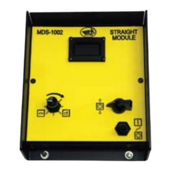
Page 14: Mds-1002 Straight Module
MDS-1002 STRAIGHT MODULE The MDS-1002 Straight Module provides direction and speed control for continuous cutting or welding. DIGITAL READOUT SPEED CONTROL CARRIAGE TRAVEL SWITCH WELD CONTACT (PLASMA) SPEED CONTROL: Sets the tractor speed from 2-120 in/min (5.1-304.8 cm/min). CARRIAGE TRAVEL SWITCH: Provides FORWARD/STOP/REVERSE direction control. Stop at limit in direction of travel &... -
Page 15: Mds-1003 Stitch Module
MDS-1003 STITCH MODULE The MDS-1003 Stitch Module provides direction and speed control for continuous welding and cutting. In addition, a stitch welding mode is provided, with adjustments for skip time (welder off), weld on time and puddle buildup/crater fill time. MDS-1003 STITCH MODULE DIGITAL READOUT... - Page 16 MDS-1003 STITCH MODULE, CONT’D. STITCH/CONTINUOUS: Selects between cyclic (Stitch) welding and continuous welding or cutting. a) CONTINUOUS - Selects continuous welding or cutting. b) STITCH - Selects the cyclic (Stitch) welding mode. This mode consists of four continuously repeated steps. 1) The machine stops moving for the selected time to perform Puddle Buildup.
-
Page 17: Mds-1004 Programmable Module
MDS-1004 PROGRAMMABLE MODULE The MDS-1004 PROGRAMMABLE MODULE provides stitch controls for welding or cutting with the Modular Drive System. All stitching parameters are set and displayed on a graphic screen. This allows each setting to be set exactly the same every time. See MDS-1004 Manual for detailed instructions. Display Controls Extra Contactor Output... - Page 18 WEAVER CONTROL MODULES MDS-1005 WEAVER CONTROL MODULE The MDS-1005 Weaver Control Module provides weave welding control functions. MDS-1005 WEAVE MODULE WEAVE AMPLITUDE WEAVE SPEED DIGITAL READOUT DWELL LEFT DWELL RIGHT STEERING CONTROL TRACTOR SPEED CARRIAGE TRAVEL CONTROL SWITCH MODE SELECTOR SWITCH WELD CONTACT START/STOP...
- Page 19 WEAVER CONTROL MODULES, CONT’D. AMPLITUDE (WEAVE): Continuously adjustable up to a 2" (51 mm) maximum weaver stroke. CARRIAGE TRAVEL SWITCH: Provides FORWARD/STOP/REVERSE direction control. DIGITAL READOUT: Three tractor display modes exist. a) PRESET SPEED - Displayed when the CARRIAGE TRAVEL SWITCH is OFF or motion is halted by a motor overload condition.
-
Page 20: Mds-1005 / Mds-1005-Dial Weaver Control Module Replacement Parts
MDS-1005 / MDS-1005-DIAL WEAVER CONTROL MODULE REPLACEMENT PARTS REPLACEMENT POTS AND SWITCHES MDS-1005 MDS-1005-DIAL Switch and Spacer MDS-1114 WELD CONTACT: Toggle Switch Boot MDS-1047 Switch and Spacer MDS-1117 CARRIAGE TRAVEL SWITCH: Toggle Switch Boot MDS-1047 DWELL RIGHT: 500K Ω Pot MDS-1053 Black Knob MDS-1018... -
Page 21: Digital Readout Calibration
DIGITAL READOUT CALIBRATION Internal Control Module adjustments enable the user to change between cm/min and in/min. The display can also be recalibrated, if required, to give an accurate speed readout. STEP 1: Remove endplate. STEP 4: Calculate the speed of the machine by measuring how far it moves in a certain amount of time. - Page 22 WPD-1100 LINEAR WEAVER INTRODUCTION The Linear Weaver and Weaver Control Module add weave welding capability to the Modular Drive System. The Linear Weaver bolts onto the front of the carriage and the Weaver Control Module plugs into the top of the Master Drive Unit.
-
Page 23: Linear Weaver / Technical Data / Dimensions
TECHNICAL DATA WPD-1100 LINEAR WEAVER Power Receives power from Master Drive. Requirements: Uses 70 additional watts. Dimensions: 7.25" L x 5.50" W x 5.37" H (184 x 140 x 137 mm) Net Weight: 13.5 lbs (6.0 kg) Shipping Weight: 16.5 lbs (7.5 kg) Speed: 2-110 in/min (51-2794 mm/min) Cycles:... -
Page 24: Linear Weaver Setup
LINEAR WEAVER SETUP 1) WEAVER CONTROL MODULE AND LINEAR WEAVER INSTALLATION The Weaver Control Module plugs into the top of the Master Drive Unit. Use a flat head screw driver to firmly secure the four corners of the module. Place the Linear Weaver on a flat surface, connector side up. Remove connector cover plate from MPD-1000. Loosen, but do not remove, the bolts that hold the Master Drive Module to the carriage. - Page 25 LINEAR WEAVER SETUP, CONT’D. 4) REMOTE CONTACTOR WIRING Connect the remote weld contactor on the Master Drive to the welding source as shown below. Pins A and B ....connection for Output #1 Pins C and D ....connection for Output #2 5) GUN AND SETUP For welding, insert the welding gun into the all-position clamp on the rack.
-
Page 26: Wpd-1100 Linear Weaver / Exploded View
WPD-1100 LINEAR WEAVER / EXPLODED VIEW... -
Page 27: Wpd-1100 Linear Weaver / Parts List
WPD-1100 LINEAR WEAVER / PARTS LIST ITEM PART NO. DESCRIPTION MOT-0002 Gear Motor (80:1) 24V BUG-1853 Machine Rack 7 1/2" (191 mm) Lg BUG-2593 Glide Flat BUG-5455 Gun Mounting Group BUG-5462 Right Angle Clamp CWO-4021 Adj Leg & Wheel Assembly CWO-4020 Fixed Leg &... - Page 28 WPD-2100 PENDULUM WEAVER II INTRODUCTION The Pendulum Weaver and Weaver Control Module add a pendulum-type weaving motion to the Modular Drive System. The Pendulum Weaver is particularly useful for weaving fillet welds in a corner joint. The weaver motor box is mounted to the front of the carriage using standard racks and rackholders. FEATURES •...
- Page 29 PENDULUM WEAVER II SETUP INSTALLATION The Weaver Control Module plugs into the Master Drive Unit. Use a flat blade screwdriver to firmly secure the four corners of the module. Remove connector cover plate from MPD-1000. Plug the Pendulum Weaver Electronics box into the front end of the Master Drive Unit.
- Page 30 SETUP AND ALIGNMENT Attach the rail parallel to the weld joint, with magnet bars or vacuum cups. Position the drive carriage on the rail - see Modular Drive instructions if necessary. Insert the welding gun into the clamp on the pendulum weaver. Adjust the racks and clamps to align the welding gun tip with the weld joint, and tighten firmly in place.
-
Page 31: Pendulum Weaver Ii / Technical Data / Dimensions
TECHNICAL DATA WPD-2100 PENDULUM WEAVER II Power Uses 70 watts, Requirements: received from Master Drive Unit. Dimensions: Electronics Box: 6.0"W x 4.38"H x 2.38"L (152 x 111 x 60.3 mm) Gearbox: 3.31"W x 4.10"H x 5.66"L (84 x 104 x 144 mm) Net Weight: 12.88 lbs (5.84 kg) Speed:*... -
Page 32: Wpd-2100 Pendulum Weaver Ii / Exploded View / Parts List
WPD-2100 PENDULUM WEAVER II / EXPLODED VIEW / PARTS LIST PARTS LIST ITEM PART NO. DESCRIPTION MUG-1634-3 Power Cable, 3' (914 mm) MDS-1029 Mounting Plate w/Screws WPD-2110 Pendulum Gear Box (Includes items 4, 5, 6) WPD-2115 Gear Box WPD-2041 Clamp Block WPD-2050 Gun Mounting Group (Includes items 7 thru 10) BUG-2234... - Page 33 WPD-2120 PENDULUM WEAVER II / ELECTRONICS / EXPLODED VIEW PARTS LIST ITEM PART NO. DESCRIPTION FAS-0104 Pan Hd Scr 4-40 x 3/8 Lg FAS-0114 Pan Hd Scr 6-32 x 3/8 Lg FAS-0225 Rnd Hd Scr 8-32 x 1/2 Lg FAS-0905 Flt Hd Soc Scr 4-40 x 1/2 Lg FAS-1305 Hex Nut 4-40...
-
Page 34: Wpd-2115 Pendulum Gear Box / Exploded View
WPD-2115 PENDULUM GEAR BOX / EXPLODED VIEW / PARTS LIST PARTS LIST ITEM PART NO. DESCRIPTION FAS-0104 Pan Hd Scr 4-40 x 3/8" FAS-0124 Pan Hd Scr 8-32 x 3/8" FAS-1305 Hex Nut 4-40 WAS-0201 #4 Internal Lock Washer WPD-1037-SWT Pot w/ Switch & Wiring WPD-2027 Motor Mounting Plate WPD-2028... - Page 35 WPD-1100 LINEAR WEAVER, WPD-2100 PENDULUM WEAVER WIRING DIAGRAM*** Notes: * The encoder section outlined is for the WPD-1000 Linear Weaver only. ** The PC Card to filter power is only used in WPD-2000 Series Pendulum Weavers. ***Wiring diagram will also work for older WPD-1000 and WPD-2000 Weavers.
-
Page 36: Carriages
CARRIAGES The MPD-1065 Releasable 12" (305 mm) and FMD-1105 12" (305 mm) Hi Flex Carriages can be placed anywhere on the track by using the knob located on the side of the carriage, which engages or disengages the wheels from the rail. The MPD-1055 18" (457 mm) Carriage provides an extended deck for mounting accessories, wire feeder, etc. -
Page 37: Detailed Setup
DETAILED SETUP 1. Install Rail The Tube Carriage is designed for use with Bent Rigid Rail (BRR) or Ring Rail. The exact outside diam- eter (OD) of the work piece, including coating, must be known when ordering rail. Minimum pipe OD is 9 inches (229 mm). -
Page 38: Mds-1055 Universal Limit Kit
MDS-1055 UNIVERSAL LIMIT KIT The MDS-1055 Universal Limit Kit is an accessory that installs between the Master Drive Unit and any of the three control modules: the *MDS-1002 Straightline, the MDS-1003 Stitch and the MDS-1005 Weaver Control Module. This limit kit adds the ability to CYCLE between limits, STOP AT LIMIT, or RAPID RETURN. All exist- ing functions of the control modules are maintained. -
Page 39: Mds-1060-_ Remote Control Cable
MDS-1060-_ REMOTE CONTROL CABLE MOUNTS TO MOUNTS TO MDS-1060-10 10' (3 m) REMOTE CONTROL CABLE CONTROL MODULE MASTER DRIVE MDS-1060-25 25' (7.6 m) REMOTE CONTROL CABLE The optional Remote Control Cable allows the operator to perform work in confined areas where it is difficult to reach the controls. -
Page 40: Accessories
MODULAR DRIVE ACCESSORIES FOR STRAIGHT LINE CUTTING: MDS-9898 MDS-3025 3-Hose 2-Hose Quick-Acting Quick-Acting Manifold Manifold MDS-1050 Machined MUG-1119-32 Rack CIR-1010-3 3-Hose Cutting Group Twin Hose Assembly Assembly 32" (813 mm) 32" (813 mm) FOR STRAIGHT LINE AND STITCH WELDING: MDS-1040 Machined Rack Welding Group FOR ALL APPLICATIONS:... -
Page 41: Aluminum Rigid Rail
ALUMINUM RIGID RAIL ALUMINUM RIGID RAIL is a high quality alloy, rigid section made to the machine tool tolerance shown in the sectional view below. The carriage drive pinion meshes with a machined gear rack that is mounted on the rail. The wheels of the carriage travel in opposed grooves at either side of the rail, locking the carriage to the rail. -
Page 42: Semi Flex Rail
SEMI-FLEX RAIL MIN. RADIUS 15' (4.6 m) SEMI-FLEX RAIL can be bent inside or outside to a minimum radius of 15' (4.6 m) or 30' (9.1 m) diameter without permanent (2.37 m) deformation. (2.37 m) AFR-3000 SEMI-FLEX RAIL replaces the old AFR-1000, 1010, 1020 and the later AFR-2000 rails. All the rack-mounting holes on the AFR-3000 Semi-Flex Rail are slotted so that the rack can slide along the rail. -
Page 43: Hi-Flex Rail
HI-FLEX RAIL The FMD Hi-Flex Rail can flex from a straight to a 30" (760 mm) radius inside or outside. The rail is made from a tempered, wear resistant, stainless steel with a steel rack. It is designed for use with the FMD Hi-Flex Carriage. -
Page 44: Standard Magnet Assemblies
STANDARD MAGNET ASSEMBLIES MAGNET PLATE ASSEMBLIES mount ARR rail quickly and conveniently right on the work surface. Magnets cannot exert maximum pull on dirty material. Remove excessive paint, scale and rust from the area on which the magnets will be placed. KEEP MAGNETS CLEAN - before positioning, wipe off magnetic particles which adhere to the poles. -
Page 45: Vacuum Support Kit
VACUUM SUPPORT KIT The standard Vacuum Support Kit, ARV-1080 consists of four (4) bars (with 8 cups) and associated hose and fittings. Some applications may require additional ARV- 1036 Vacuum Support Bar assemblies. ARV-1051 ARV-2020 Vacuum Pump Kit 120V ARV-2030 Vacuum Pump Kit 240V ARV-1036 ARV-1036 VACUUM SUPPORT BAR / EXPLODED VIEW / PARTS LIST VACUUM CUPS are used for mounting the rail to... - Page 46 VACUUM SUPPORT KIT, CONT’D. VACUUM PUMP / EXPLODED VIEW / PARTS LIST ARV-2020 VACUUM PUMP KIT, 120VAC 60HZ/1PH ARV-2030 VACUUM PUMP KIT, 240 VAC 50 HZ/1PH The VACUUM PUMP KITS are 1/6 HP units that provide 15" (381 mm) Hg on continuous duty.
- Page 47 MODULAR DRIVE SYSTEM TROUBLESHOOTING GUIDE The Modular Drive System allows the user to mix and match components to custom build a machine for an application. The resulting ability to replace and remove individual components while troubleshooting significantly reduces the time and effort required to troubleshoot the system. The recommended trouble- shooting procedure is as follows: 1) Verify that there are no loose electrical or mechanical connections.
-
Page 48: Troubleshooting Guide
TROUBLESHOOTING GUIDE, CONT’D. PROBLEM POSSIBLE CAUSE TEST BASE SYSTEM TEST PROCEDURE / REMEDY Speed display Power switch is Turn ON the main ON/OFF switch located in the power entry is not lit and OFF. module. (see Figure 1) tractor does not run. - Page 49 TROUBLESHOOTING GUIDE, CONT’D. PROBLEM POSSIBLE CAUSE TEST BASE SYSTEM TEST PROCEDURE / REMEDY Bad power supply. Turn on the main power. The green LEDs L1 and L2 (see Figure 1) will light if the power supply is OK. If the LEDs are off, unplug the power supply output connector (see Figure 1).
- Page 50 TROUBLESHOOTING GUIDE, CONT’D. PROBLEM POSSIBLE CAUSE TEST BASE SYSTEM TEST PROCEDURE / REMEDY Faulty motor. Disconnect the motor leads. Apply 2 to 8 volts DC across the motor leads. Verify that the motor spins. Faulty control Install one voltmeter lead on TP4 and the other lead on TP5. Turn module, speed card, on the main power.
- Page 51 TROUBLESHOOTING GUIDE, CONT’D. PROBLEM POSSIBLE CAUSE TEST BASE SYSTEM TEST PROCEDURE / REMEDY Linear Weaver Bad control card or Set the weaver control module MODE SELECT switch to NO does not move. bad weaver. WEAVE and the START/STOP switch to START. Turn the weave speed up to max.
- Page 52 TROUBLESHOOTING GUIDE, CONT’D. PROBLEM POSSIBLE CAUSE TEST BASE SYSTEM TEST PROCEDURE / REMEDY Pendulum shaft Bad control module, Set the weaver control module MODE SELECT switch to RUN does not move. damaged power (no weave) and the START/STOP switch to START. Turn the cable, bad speed WEAVE SPEED to maximum.
- Page 53 TROUBLESHOOTING GUIDE, CONT’D. PROBLEM POSSIBLE CAUSE BASE SYSTEM TEST PROCEDURE / REMEDY Chatter from Clutch improperly Knob should be seated firmly against drive unit. Turn drive clutch knob main drive unit engaged fully clockwise while gently rocking the machine forward and backward to fully engage the drive pinion.
- Page 54 TROUBLESHOOTING GUIDE, CONT’D. The Modular Drive System is equipped with internal fault diagnostic LEDs and test Points 10 Speed troubleshooting as shown below. Test point evaluation should be performed by a qualified technician using a volt meter. If a qualified technician is not available, return the unit to the factory for repair.
- Page 55 TROUBLESHOOTING GUIDE, CONT’D. ACCESSORY PORT CHASSIS GROUND Figure 2. Master Drive Accessory Port Figure 3. Procedure for Opening the Master Drive Case: 1. Unplug the power cord. 3. Remove ONLY the seven screws as shown. 2. Unbolt the Master Drive from the carriage.
- Page 56 UNIVERSAL LIMIT KIT TROUBLESHOOTING This Troubleshooting section details troubleshooting the Universal Limit Kit. See the Modular Drive System Troubleshooting Guide for troubleshooting all other components. Recommended Troubleshooting Procedure: 1) If using the Universal Limit Kit with the MDS-1001 Straight Module, the CYCLE SELECTION switch on the Control Module must be in the BASIC FORWARD/REVERSE position for the machine to operate property.
- Page 57 SPK-1000 MODULAR DRIVE SYSTEM 120V SPARE PARTS KIT / PARTS LIST PART NO. DESCRIPTION 100-0422 POWER ENTRY MODULE MOUNTING PLATE 100-0425 FILTERED POWER ENTRY MODULE HARNESS BUG-2959 WHEEL ASSEMBLY BUG-9454 V-LOCK 110VAC CORD 2M MPD-1000 HARDWARE KIT 100-0311 FLT HD SOC CAP SCR 6-32 x 3/4 FAS-0112 PAN HD SLT 6-32 x 1/4 BLACK FAS-0114...
- Page 58 SPK-1004 MODULAR DRIVE SYSTEM 42V SPARE PARTS KIT / PARTS LIST PART NO. DESCRIPTION 100-0422 POWER ENTRY MODULE MOUNTING PLATE 100-0425 FILTERED POWER ENTRY MODULE HARNESS BUG-2959 WHEEL ASSEMBLY BUG-9454-42 V-LOCK POWER CORD, 42V MPD-1000-HW HARDWARE KIT 100-0311 FLT HD SOC CAP SCR 6-32 x 3/4 FAS-0112 PAN HD SLT 6-32 x 1/4 BLACK FAS-0114...
- Page 59 BUG-O SYSTEMS INTERNATIONAL EC DECLARATION OF CONFORMITY Manufacturer and technical documentation holder: Bug-O Systems International a Division of Weld Tooling Corporation 280 Technology Drive Canonsburg, PA 15317-9564 Hereby declare that machinery: Modular Drive System, including options and accessories Sales codes:...
-
Page 60: Warranty
WARRANTY Model _____________________________ Serial No. __________________________ Limited 3-Year Warranty Date Purchased: ____________________ Where Purchased:___________________ For a period ending one (1) year from the date of invoice, Manufacturer warrants that any new ma- chine or part is free from defects in materials and workmanship and Manufacturer agrees to repair or replace at its option, any defective part or machine.
Need help?
Do you have a question about the BUG-O SYSTEMS MPD-1000 and is the answer not in the manual?
Questions and answers