
Summary of Contents for VPixx Technologies VideoBahn TRACKPixx3
- Page 1 TRACKPixx3 (VPX-TRK-3410C) Installation Guide Version 1.4 Phone : (514) 328-7499 1 (844) 488-7499 - Toll Free USA/Canada EMAIL: support@vpixx.com www.vpixx.com...
- Page 3 TRACKPixx3 Installation Guide IMPORTANT VPixx Technologies Inc. reserves the right to modify or otherwise update this document without notice as required by a constantly evolving marketplace, client requests or to adapt to new progress or constraints in engineering or manufacturing technology. The information contained in this document may change without prior notice.
-
Page 4: Table Of Contents
Console Monitor and Stimulus Display power connections ..................... 17 Chinrest installation ................................17 TRACKPixx3 camera rear LED............................17 Software installation instructions ............................17 Maintenance ..................................18 Cleaning the TRACKPixx3 ..............................18 Warranty ....................................18 Specifications ..................................19 Copyright © 2020 VPixx Technologies Inc. All Rights Reserved... -
Page 5: List Of Tables
TRACKPixx3 Installation Guide List of Tables TABLE 1 – DOCUMENT HISTORY................................1 TABLE 2 – DOCUMENT ICONS ................................... 1 TABLE 3 – TRACKPIXX3 SETUP CONNECTION DESCRIPTIONS ........................10 TABLE 4 - SPECIFICATIONS ..................................19 Table of Figures FIGURE 1 - TYPICAL TRACKPIXX3 SYSTEM SETUP ............................ 10 FIGURE 2 - TYPICAL TRACKPIXX3 SHORT-RANGE SYSTEM SETUP ...................... -
Page 6: Overview
E-mail to support@vpixx.com By creating your MyVPixx account on the VPixx Technologies website, you will have access to additional product documentation, demos, source code examples and the latest firmware and software drivers. The TRACKPixx3 device is suitable only for research and is not designed for medical applications or for diagnostic purposes. -
Page 7: Compliance Information
TRACKPixx3 Installation Guide Compliance information The VideoBahn interface on the TRACKPixx3 uses a fiber optic module whose manufacturer provides a certificate of conformance for standard IEC 60825-1 Ed. 3 (2014) CLASS 1 LED DEVICE IEC 60825-1 Ed. 3 (2014) For the United States of America This device complies with part 15 subpart B of FCC rules. -
Page 8: For European Countries
Supplementary Information: To remain CE compliant, only CE compliant parts should be used with this product. Maintaining CE compliance also requires proper cable and cabling techniques. VPixx Technologies will not retest systems or components that have been modified by customers. -
Page 9: Declaration Of Rohs Compliance
The mark indicates the requirement NOT to dispose of the equipment as unsorted municipal waste. For support@vpixx.com more information call VPixx Technologies Inc. or email us at Declaration of RoHS Compliance This product has been designed and manufactured in compliance with Directive 2011/65/EU of the European Parliament and the Council on restriction of the use of certain hazardous substances in electrical and electronic equipment (RoHS Directive). -
Page 10: Warnings, Safety Information & Usage Notes
CISPR WARNING: this is a Class A product. In domestic environments, this product may cause radio interference in which case the user may be required to take adequate measures. Use of controls or procedures other than those specified herein may result in hazardous radiation exposure. Copyright © 2020 VPixx Technologies Inc. All Rights Reserved... -
Page 11: Safety Information
Ensure that air circulation surrounds all system components. • In the event of failure, the TRACKPixx3 and InfraRed Illuminator devices should be replaced. There are no user serviceable/adjustable parts inside. Contact VPixx Technologies Inc. for repair or replacement as required. -
Page 12: Typical Setup
Power cable from DATAPixx3 power OUTPUT connector to TRACKPixx3 camera LEMO power connector Cable from InfraRed Illuminator to TRACKPixx3 camera infrared interface connector DisplayPort cable from DATAPixx3 OUT1 to stimulus display Copyright © 2020 VPixx Technologies Inc. All Rights Reserved... -
Page 13: Setup - Trackpixx3 Short-Range System
Setup – TRACKPixx3 Short-Range System The following illustration details a typical setup and subject placement for a TRACKPixx3 Short-Range System (using either VPixx Technologies’ InfraRed Short-Range Illuminator or InfraRed Short-Range 940nm Illuminator). Notice the suggested distance between the subject and the camera. -
Page 14: Installation Steps
The Control Room computer to the DATAPixx3 DisplayPort IN1 (connection The DATAPixx3 DisplayPort OUT2 to the console monitor DisplayPort input (connection c. The DATAPixx3 OUT1 to the stimulus display (connection Copyright © 2020 VPixx Technologies Inc. All Rights Reserved... -
Page 15: Camera And Infrared Illuminator Installation And Connections
TRACKPixx3 Installation Guide 4. Connect a power cable from: a. The DATAPixx3 +12 V OUTPUT (8 pins) to the TRACKPixx3 camera (connection b. The TRACKPixx3 camera’s infrared interface connector to the InfraRed Illuminator (connection c. Finally, connect the DATAPixx3’s supplied power cable to its power supply and the power supply to your facility’s power outlet. -
Page 16: Figure 5 - Cable Connector Red Dot
InfraRed Illuminator device and arrange them in the exact position required by your application. The procedure to mount either the TRACKPixx3 or InfraRed Illuminator device to the mounting apparatus is the same. Copyright © 2020 VPixx Technologies Inc. All Rights Reserved... -
Page 17: Lens Installation
TRACKPixx3 Installation Guide 4. Slide the device along the mounting apparatus’ support arm. 5. Once in its desired location along the mounting arm, tighten the mounting screw at the back of the device to secure it in place. Figure 7 - Mounting screw 6. -
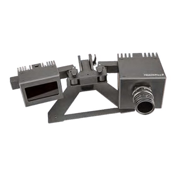
Page 18: Figure 9 - Trackpixx3 Camera (With Lens)
2. Once the camera lens has been firmly installed and the system is operational, use the focus adjustment ring and light aperture adjustment ring on the lens (refer to Figure 10) to adjust the image focus and brightness recorded by the camera. Copyright © 2020 VPixx Technologies Inc. All Rights Reserved... -
Page 19: Console Monitor And Stimulus Display Power Connections
TRACKPixx3 Installation Guide Console Monitor and Stimulus Display power connections Use the appropriate power cables to connect the console monitor and the Stimulus display. Chinrest installation If your TRACKPixx3 package includes the optional chinrest, install it at a proper distance from the TRACKPixx3 camera according to the setup diagram appropriate to your experiment (Figure 2 or Figure 3). -
Page 20: Maintenance
Do not use cleaners that contain any petroleum-based materials such as benzene, thinner, or any volatile substance Warranty The TRACKPixx3 is warranted against manufacturing defects in materials and workmanship for a period of two years from the date of purchase. Copyright © 2020 VPixx Technologies Inc. All Rights Reserved... -
Page 21: Specifications
TRACKPixx3 Installation Guide Specifications Table 4 - Specifications Installation Type Tabletop Short-Range Tabletop Long-Range Tabletop remote Sampling Rate 2 kHz Binocular Eye Tracking Method Pupil with corneal reflection Accuracy 0.20˚ - 0.60˚ Spatial Resolution 0.01˚ Tracking Precision with 0.04˚ 0.04˚ 0.05˚... - Page 22 VPixx Technologies Inc. 630 Clairevue West suite 301 Saint-Bruno, Qc Canada, J3V 6B4 TEL/FAX: (514) 328-7499 TOLL FREE: (844) 488-7499 (USA/CANADA) EMAIL: sales@vpixx.com...
Need help?
Do you have a question about the VideoBahn TRACKPixx3 and is the answer not in the manual?
Questions and answers