
Summary of Contents for Bentel Security VectorBRIDGE
- Page 1 VectorBRIDGE Sistema Universale per Dispositivi via Radio Universal Wireless Device System MANUALE DI INSTALLAZIONE INSTALLATION MANUAL ® MADE ITALY...
- Page 2 Receiver – allontanare la Centrale e/o l’Interfaccia dal Ricevitore. – Move the Control panel and/or Interface away from the Receiver. Con la presente Bentel Security dichiara che il di- spositivo VectorBRIDGE è conforme ai requisiti Hereby, Bentel...
-
Page 3: Table Of Contents
INDICE INTRODUZIONE PROGRAMMAZIONE DELL’INTERFACCIA Caratteristiche Generali ........5 Descrizione ............5 Collegamento della Tastiera ......27 Interfaccia BPI ............. 6 Supervisione Zona ........... 27 Interfaccia Universale ......... 6 Finestra Supervisione ........28 Display ..............8 Lingua ..............28 Memoria ............... 8 Segnali Ausiliari via BPI ........ - Page 4 AVVERTENZE: Leggere Attentamente Note per gli Installatori quando il fuoco si sviluppa in un camino, sui muri o sui tetti, o in altri luoghi chiusi Queste avvertenze contengono informazioni importanti. Come unico individuo in da porte. I Rivelatori di Fumo potrebbero non rilevare il fumo causato da incendi contatto con gli utenti del sistema, è...
-
Page 5: Introduzione
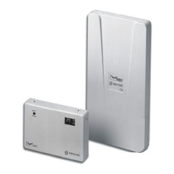
Protezione contro l’apertura (Ricevitore e Interfaccia) e lo strappo (solo Ricevitore). Descrizione VectorBRIDGE è un sistema per il “collegamento” di dispositivi via radio con centrali antifurto cablate (vedere figura 1). Esso è costituito da un Ricevitore (VectorRX) e da un’Interfaccia (VectorBRIDGE). -
Page 6: Interfaccia Bpi
Segnali Ausiliari via BPI sia abilitata. Interfaccia Universale Per il “collegamento” dei dispositivi via radio con centrali convenzionali, VectorBRIDGE è dotato di un’interfaccia Universale costituita da 16 uscite e 2 ingressi come descritto di seguito (vedere la colonna Interf. Universale della Tabella 1). - Page 7 Ins. Parziale da Radiochiave n. 01 Inserimento Tipo A Attivazione uscita tramite Attivatore Ins. Parziale da Radiochiave n. 04 su Inseritore 16 Tabella 1 Eventi gestiti da VectorBRIDGE e azioni corrispondenti sull’Interfaccia BPI, sull’Interfaccia Universale, sui Display e nella Memoria INTRODUZIONE...
-
Page 8: Display
+ Le Istruzioni per l’Utente devono essere lette anche dall’installatore poiché con- tengono informazioni importanti per l’installazione del sistema. Caratteristiche Tecniche La tabella seguente mostra le caratteristiche tecniche di VectorRX e VectorBRIDGE. VectorRX VectorBRIDGE Alimentazione – 13,8 V_ Assorbimento –... -
Page 9: I Dentificazione Delle Parti
I DENTIFICAZIONE DELLE PARTI In questo capitolo sono descritte le parti dei dispositivi del sistema VectorBRIDGE. Nel manuale, i numeri in grassetto fanno riferimento alle figure e alle tabelle presenti in questo capitolo, salvo indicazioni diverse. PARTE DESCRIZIONE 1 Pulsante PROG per l'accesso alla programmazione... - Page 10 N O W IRIN G IN T H IS AREA ® ATN1 GND11 ATN1 GND1 GND2 GND22 RED BLK YEL GRN Figura 3 Parti del Ricevitore Sistema Universale per Dispositivi via Radio VectorBRIDGE...
- Page 11 PARTE DESCRIZIONE 16 Ganci (2) per la chiusura del Ricevitore 17 Fori (3) per il fissaggio (ø 4,6 mm) 18 Antenne (2) 19 Microprocessori (2) 20 Deviatore antistrappo 21 Pulsante antisabotaggio 22 Viti di chiusura (2) 23 Apertura per il passaggio dei cavi (10 x 6,4 mm) 24 Gancio a molla per la chiusura del Ricevitore 25 Morsettiera per il collegamento all'Interfaccia PARTE DESCRIZIONE...
- Page 12 BPI 5V SNATCH – + CR – BPI 5V SNATCH – Figura 5 Cavo BPI-LINK (a) e parti della Tastiera MIA-S: b) vista esterna senza sportel- lo; c) vista interna Sistema Universale per Dispositivi via Radio VectorBRIDGE...
-
Page 13: Installazione
INSTALLAZIONE L’installazione del sistema VectorBRIDGE può essere suddivisa in tre passi principali: r Configurazione dei Dispositivi via Radio r Piazzamento dei Dispositivi via Radio r Montaggio dei Dispositivi via Radio, del Ricevitore e dell’Interfaccia Scelta del luogo per il montaggio del Ricevitore + Fissare il Ricevitore e i Dispositivi via Radio dopo che è... -
Page 14: Configurazione Dispositivi Via Radio
6 Trascrivere l'ESN e la zona alla quale è stato assegnato nella Tabella A5 del paragrafo “Tabelle di Programmazione”. 7 Ripetere i passi dal n. 3 al n. 6 finché non sono stati messi in configurazione tutti i Sensori, quindi premere per tornare al passo n. 2. Sistema Universale per Dispositivi via Radio VectorBRIDGE... - Page 15 + I Sensori non funzionano correttamente finché non viene completata la pro- grammazione (vedere il capitolo “PROGRAMMAZIONE DELL’INTERFACCIA”). n n Configurazione Radiochiavi Sel. Sel._ _ operazione_ _ operazione 1 Premere il pulsante PROG (1) dell’Interfaccia per Superv. Superv._ _ Zona____ Zona ____ almeno 5 secondi.
-
Page 16: Piazzamento Dei Sensori Via Radio
Se molti Sensori danno un risultato cattivo, potrebbe essere necessario sposta- re il Ricevitore in una posizione migliore (leggere il paragrafo “Scelta del luogo per il montaggio del Ricevitore” per dei suggerimenti su dove montare il Ricevi- tore). Sistema Universale per Dispositivi via Radio VectorBRIDGE... -
Page 17: Montaggio Del Ricevitore
n n Attivazione dei Sensori via Radio AMD10A/AMD10 Per effettuare il Piazzamento del AMD10A e del AMD10, rimuovere il sensore dalla staffa e riagganciarlo. Quando il sensore viene riagganciato alla staffa, la sua spia lampeggia velocemente 5 volte per indicare che esso ha inviato una trasmissione. -
Page 18: Montaggio Dell'interfaccia
Ø per collegare l’Interfaccia al Ricevitore non possono essere usati più di 50 metri di cavo; Ø se si utilizza l’interfaccia Universale di VectorBRIDGE, possono essere neces- sari fino a 20 fili per il collegamento con la Centrale, quindi, in questo caso, è... -
Page 19: Preparazione Della Tastiera Per La Programmazione
+ Collegare questi morsetti SOLO quando si usa l’interfaccia Universale di VectorBRIDGE. Viceversa, NON collegare questi morsetti quando si usa l’inter- faccia BPI di VectorBRIDGE poiché quest’ultima sarà alimentata dal bus BPI della Centrale, tramite i morsetti + e –. - Page 20 + Il deviatore 8 dell’Interfaccia può essere escluso inserendo il ponticello 7. Collegare questa Uscita alla fine della linea antisabotaggio della Centrale. Se la linea antisabotaggio della Centrale e bilanciata, collegare il Resistore di Bilan- ciamento a questa uscita. Sistema Universale per Dispositivi via Radio VectorBRIDGE...
- Page 21 Batteria Scarica L’Uscita si attiva quando il livello della batteria di un Sensore è basso. L’Uscita torna a riposo quando non ci sono più Sensori con la batteria scarica. Collegare questa Uscita ad una zona d’ingresso della Centrale oppure all’in- gresso di un dispositivo telefonico (Avvisatore Telefonico, Comunicatore Tele- fonico, ecc.) programmati per comunicare via telefono che c’è...
- Page 22 L’Uscita torna a riposo quando tornano a riposo tutte le Zone assegnate ad essa. (Vedere “Mappatura Zone” nel capitolo “PROGRAMMAZIONE DELL’IN- TERFACCIA”). Collegare queste Uscite alle Linee d’Ingresso della Centrale. Figura 5 Collegamento del Ricevitore all’Interfaccia Sistema Universale per Dispositivi via Radio VectorBRIDGE...
-
Page 23: Collegamento Del Ricevitore
BLK; NON usare più di 50 metri di cavo. Collegamento con le centrali Omnia e Academy40 Per usare l’interfaccia BPI di VectorBRIDGE, collegare la sua morsettiera 13 al bus BPI della Centrale come mostrato in figura 7. -
Page 24: Collegamento Con Centrali Antifurto Cablate
Collegamento con Centrali Antifurto Cablate In figura 8 è mostrato un esempio di collegamento con una centrale cablata tramite l’interfaccia Universale di VectorBRIDGE. + Per il collegamento usare cavo schermato: collegare lo schermo solo dal lato della Centrale, alla massa. -
Page 25: Livello Bpi Dell'interfaccia
Si presume che la Linea d’Ingresso della Centrale L7 sia di tipo 24 Ore e sia programmata per attivare le uscite di allarme (Sirene) e per segnalare via tele- fono, all’installatore e/o alla centrale di vigilanza, un tentativo di sabotaggio del sistema, tramite disturbi radio. -
Page 26: Sostituzione Di Un Dispositivo Via Radio
Per rimuovere una Radiochiave, leggere “Configurazione Radiochiavi” nel pa- ragrafo “Configurazione Dispositivi via Radio”: Ø al passo n. 3, selezionare il “posto” al quale è assegnata la Radiochiave che deve essere rimossa; Ø al passo n. 4, digitare tutti zeri. Sistema Universale per Dispositivi via Radio VectorBRIDGE... -
Page 27: Programmazione Dell'interfaccia
PROGRAMMAZIONE DELL’INTERFACCIA La programmazione del sistema VectorBRIDGE si effettua tramite la tastiera OmniaTAST-R o MIA-S come descritto in questo capitolo. Collegamento della Tastiera 1 Preparare la Tastiera per la programmazione come descritto nel paragrafo “Pre- parazione della Tastiera per la programmazione” del capitolo “INSTALLAZIONE”. -
Page 28: Finestra Supervisione
Italiano Italiano________ ________ desiderata: trascrivere la lingua selezionata nella Tabella A3 del paragrafo "Tabelle di Programmazione". 3 Premere per confermare la scelta effettuata oppure premere abbandonare. Tornare al passo n. 1. Sistema Universale per Dispositivi via Radio VectorBRIDGE... -
Page 29: Segnali Ausiliari Via Bpi
Segnali Ausiliari via BPI Se le opzioni Segnali Ausiliari via BPI dell’Interfaccia e della Centrale sono abilitate (vedere “Segnali Ausiliari via BPI” del capitolo “PROGRAMMAZIONE DELLA CENTRALE”), le segnalazioni mostrate nella tabella seguente (colonna SEGNALI AUSILIARI) vengono riportate sul bus BPI dagli eventi mostrati nella tabella seguente (colonna EVENTI BPI). -
Page 30: Numero Di Zone Via Bpi
Numero di Zone via BPI Quando l’interfaccia BPI di VectorBRIDGE viene collegata al bus delle centrale Omnia o Academy40, gli Allarmi e i Sabotaggi delle Zone dell’Interfaccia mostrati nelle colonne ALLARME e SABOTAG. della tabella seguente, sono segnalati dagli eventi della Centrale mostrati nelle colonne EVENTI BPI della tabella seguente. -
Page 31: Usa Mem Per I Morsetti K
Usa MEM per i Morsetti K Questa opzione determina il funzionamento delle uscite KA, KD e KS dell’Interfaccia. Ø Se l’opzione è disabilitata (preimpostazione), le richieste di INSERIMENTO, IN- SERIMENTO PARZIALE e DISINSERIMENTO da Radiochiave, provocano l’attiva- zione rispettivamente delle uscite KA, KD e KS. Ø... -
Page 32: Stato Off Uscite
Dati_ _ Dati di_ _ Fabbrica Fabbrica 2 Premere per ripristinare i Dati di Fabbrica: l'interfaccia Eseguo? Eseguo?_________ _________ esce automaticamente dalla programmazione. Premere per abbandonare e tornare al passo precedente. Sistema Universale per Dispositivi via Radio VectorBRIDGE... -
Page 33: Programmazione Della Centrale
PROGRAMMAZIONE DELLA CENTRALE Per usare l’interfaccia BPI di VectorBRIDGE, la Centrale (Omnia o Academy40) deve essere programmata come descritto in questo capitolo. Prima di tutto si deve selezionare l’opzione VectorBRIDGE nel riquadro Via Radio della pagina Configurazione, poi si devono effettuare le altre imposta- zioni riguardanti i Dispositivi via Radio, come descritto di seguito. - Page 34 24 Sensori via Radio al massimo o 20, se l'opzione Segnali Ausiliari via BPI è abilitata (vedere "Segnali Ausiliari via BPI" nel capitolo "PROGRAMMAZIONE DELL'INTERFACCIA") Tabella 3 Espansioni d’Ingresso riservate ai Sensori via Radio Sistema Universale per Dispositivi via Radio VectorBRIDGE...
-
Page 35: Segnali Ausiliari Via Bpi
Eventi-Azioni Gli eventi di Allarme zona n e Sabotaggio zona n relativi alle Zone Radio, diventano Allarme Zona Radio n e Sabotaggio Zona Radio n, dove n è il numero della Zona corrispondente dell’Interfaccia. Gli eventi Allarme zona 32 e Sabotaggio zona 32 diventano Riservato Via Radio e non sono utilizzabili. - Page 36 Gli eventi elencati nella tabella seguente vengono riservati ai Dispositivi via Radio poiché, essendo provocati anche dai Segnali Ausiliari, darebbero delle segnalazioni errate. Allarme 24h centrale Allarme Generico+Sabot. centrale Allarme Generico centrale Memoria globale di allarme Sistema Universale per Dispositivi via Radio VectorBRIDGE...
-
Page 37: Radiochiavi Via Bpi
L’Inseritore n. 16 viene riservato alle Radiochiavi, quindi, questo Inseritore non può essere collegato al bus BPI della Centrale. All’Inseritore n. 16 viene assegnata la Descrizione VectorBRIDGE. L’inserimento Tipo B (riga indicata dal Punto VERDE) dell’Inseritore n. 16 non può essere programmato in quanto non è gestito dalle Radiochiavi. - Page 38 Attivatore, significa che le Radiochiavi sono state programmate correttamente, altrimenti, spostarsi in un altro punto e riprovare. Abilitazione L’abilitazione o la disabilitazione dell’Attivatore emulato dalle Radiochiavi, abilita o disabilita TUTTE le Radiochiavi. Sistema Universale per Dispositivi via Radio VectorBRIDGE...
-
Page 39: Appendice
APPENDICE Tabelle di Programmazione Ditta: Nome: Cognome: Indirizzo: CAP: Città: Provincia: Stato: Tel.: Cell.: Fax: E-mail: Note: Tabella A1 Dati Anagrafici Uscite A1 A2 A3 A4 A5 A6 A7 A8 TMP BAT MEM JAM KA KD KS KH Programmazione Preimpostazione Tabella A2 Stato OFF delle Uscite Descrizione Programmazione... - Page 40 ZONA N. DESCRIZIONE ZONA SUPERV. A1 A2 A3 A4 A5 A6 A7 A8 default 0 0 0 0 0 0 — Abilitata — — — — — — — — Tabella A5 Programmazione Zone Sistema Universale per Dispositivi via Radio VectorBRIDGE...
-
Page 41: Linee Guida Per Il Posizionamento Dei Rivelatori Di Fumo
Linee Guida per il Posizionamento dei Rivelatori di Fumo Numerose ricerche hanno dimostrato che gli in- cendi più gravi nelle abitazioni generano fumo in maggiore o minore misura. Esperimenti con incen- di tipici nelle abitazioni indicano che in molti casi quantità... -
Page 42: Amd10: Sensore Piroelettrico Via Radio Con Batterie Al Litio
FAST a SLOW spostare il Jumper sui pin come mostrato nella figura 2. Bassofondo per fori di fissaggio Jumper J1 posizionato su FAST ad angolo Fig. 1 - Staffa Fig. 2 - Jumper Sistema Universale per Dispositivi via Radio VectorBRIDGE... - Page 43 n n Interruzione per alto traffico pisce continuamente il movimento e accende il LED Per prolungare la durata delle batterie, il senso- rosso. Dopo 5 secondi il sensore manderà un se- re usa una caratteristica chiamata Interruzione gnale alla centrale e il LED lampeggerà rapidamente per Alto Traffico.
-
Page 44: Amc10: Contatto Magnetico
PCB, poiché si può danneggiare l’altro di sei. Fare riferimento al paragrafo “Confi- il ripetitore. gurazione dei dispositivi e pianificazione del siste- ma” per le informazioni sul numero di serie che dovrà essere configurato. Sistema Universale per Dispositivi via Radio VectorBRIDGE... -
Page 45: Arc10: Radiochiave
ARC10: Radiochiave n n Caratteristiche Generali L’ARC10 è una chiave elettronica che permette di inserire e disinserire il sistema di sicurezza, così pure altre funzioni gestite da tastiera ed è così piccola che si può tenere in un taschino. In accor- do con l’installatore si può... - Page 46 Litio può causare svilup- ricaricare le batterie esauste. po di calore, esplosione o fuoco, e quindi può essere causa di lesioni alle persone. + + Smaltire le batterie usate solo nei siti pre- disposti. Sistema Universale per Dispositivi via Radio VectorBRIDGE...
- Page 47 Italiano English VectorBRIDGE Sistema Universale per Dispositivi via Radio Universal Wireless Device System ISTRUZIONI PER L’UTENTE USER’S INSTRUCTIONS ® MADE ITALY BS EN ISO 9001...
- Page 48 Italiano English Il Vostro installatore ha installato un sistema di This Wireless system includes a Receiver, an sicurezza via radio. Questo sistema è costituito da Interface and a number of W ireless Sensors and un Ricevitore, da un’Intefaccia, da Sensori via Ra- Keys.
- Page 49 Italiano English Visualizzazione della Memoria View Memory Se i display dell’Interfaccia mostrano la lettera b The letter b and a dash (-) on the Interface dis- e un trattino, significa che l’Interfaccia ha memo- play indicates that at least one of the following rizzato almeno uno dei seguenti eventi: Allarme events has been recorded on the event memory.
- Page 50 Italiano English 4 Premere brevemente il pulsante R/S: i display 4 Press R/S briefly: the letter L on the display mostrano la lettera L per indicare che vengono stands for Low Battery. If Low Battery events mostrati i sensori con batteria scarica. Saranno have been recorded the letter f will be followed mostrati ciclicamente i sensori con batteria sca- repeatedly by the numbers (1 through 31) of the...
- Page 51 Use MEM for Terminal K ........79 Zone Mapping ........... 79 PARTS IDENTIFICATION Standby for Outs ..........80 Factory data (Default Programming) ....80 INSTALLING VECTORBRIDGE PROGRAMMING THE Choosing a Mounting Location ......61 CONTROL PANEL Enrolling and Placement of Wireless Devices . 61 Number of Zones on BPI ........
- Page 52 An alarm system also is not a substitute for property owners, renters, or other occupants to act prudently to prevent or minimize the harmful effects of an emergency situation. Universal Wireless Device System VectorBRIDGE...
-
Page 53: Introduction
The VectorBRIDGE system allows wireless devices (sensors and wireless keys) to communicate with hardwired Burglar panels (see Figure 1). The VectorBRIDGE kit includes a Receiver (VectorRX) and an Interface module (VectorBRIDGE). The Receiver will transmit W ireless device signal to the Interface module. -
Page 54: Bpi Interfacing
Omnia, Omnia840 and Academy40 control panels. The BPI bus will simulate Input expander zones, as shown in Table 1. + If the Auxiliary Signals on BPI option is enabled, VectorBRIDGE will simulate the Input expander Zones shown in brackets in the BPI INTERFACING column in Table 1. - Page 55 Type A Arming Activates Output by Digital key Partition Arm. by Wireless key no. 04 on key reader 16 Table 1 Events managed by VectorBRIDGE and corresponding actions on the BPI, and Universal Interfacing terminal boards, Display and Memory INTRODUCTION...
-
Page 56: Display
The Installer must fill in Table U1 in the insert before handing it over to the User. Technical Specifications The following table shows the technical specifications of VectorRX and VectorBRIDGE. VectorRX VectorBRIDGE Power Supply –... -
Page 57: Parts Identification
PARTS IDENTIFICATION This section describes the VectorBRIDGE device parts. The numbers in bold- face in the following Parts Descriptions Tables refer to the parts shown in the figures in this section. PART DESCRIPTION 1 PROG key (Accesses Programming) 2 R/S key (Views and Deletes Memory) - Page 58 N O W IRIN G IN T H IS AREA ® ATN1 GND11 ATN1 GND1 GND2 GND22 RED BLK YEL GRN Figure 3 Receiver Parts Universal Wireless Device System VectorBRIDGE...
- Page 59 PART DESCRIPTION 16 Spring catch slot 17 Anchor Holes (3) ø 4.6 mm 18 Antenna (2) 19 Microprocessors (2) 20 Snatch Switch 21 Tamper Switch 22 Closure Screws (2) 23 Wire entry 10 x 6.4 mm 24 Spring catch 25 Interface terminal board PART DESCRIPTION 26 Cover Screws (4) 27 Backlighted LCD Display (16 columns —...
- Page 60 BPI 5V SNATCH – + CR – BPI 5V SNATCH – Figure 5 BPI-LINK cable (a) MIA-S Keypad Parts: b) External view (Flip down) c) Internal view Universal Wireless Device System VectorBRIDGE...
-
Page 61: Installing Vectorbridge
INSTALLING VECTORBRIDGE There are three main steps to follow when installing VectorBRIDGE: r Enrolling Wireless Devices r Testing the placement of Wireless Devices r Mounting the Vector and Wireless Devices Choosing a Mounting Location + Mount the receiver and wireless devices after the placement tests. -
Page 62: Enrolling Wireless Devices
7 Repeat steps 3 to 6 until all the Sensors have been enrolled, then press go back to step 2. + The sensors will not work properly until programming is completed (refer to the “PROGRAMMING THE INTERFACE” section). Universal Wireless Device System VectorBRIDGE... - Page 63 6 Record the serial number, and the assigned Keyfob number in Table A4 in the Programming Sheets section. 7 Repeat steps 3 to 6 until all the Wireless keys have been enrolled, then press to go back to step 2. INSTALLING VECTORBRIDGE...
-
Page 64: Placement Of Wireless Sensors
+ Do not mount Wireless Sensors in locations that produce bad results. If several devices produce “Bad” results, it may be necessary to move the Re- ceiver to another location (refer to “Choosing a Mounting Location” for instruc- tions). Universal Wireless Device System VectorBRIDGE... -
Page 65: Mounting The Receiver
17 then drill the screw holes. + Be careful to avoid conduits and plumbing when drilling. 6 Place the backplate in the proposed placement, pull the wires through the wire entry 23, then secure the backplate to the wall (use anchor screws). INSTALLING VECTORBRIDGE... -
Page 66: Mounting The Interface
6 Complete the wiring. Leave the power connection to last. 7 Power up. 8 Program the Interface (refer to the “PROGRAMMING THE INTERFACE” section). 9 Attach the frontplate to the top of the backplate, then tighten the screw 11. Universal Wireless Device System VectorBRIDGE... -
Page 67: Preparing The Keypad
+ These terminals should be connected ONLY when using the Universal Inter- facing terminal board. Do not connect these terminals when using the BPI Interfacing terminal board, as it will be powered by the BPI bus of the Control Panel, through terminals “+” and “–”. INSTALLING VECTORBRIDGE... - Page 68 + The Interface Tamper switch 8 can be disabled by connecting jumper 7. Connect the TMP Output to the end of the Control panel Tamper line. If the Control panel Tamper line is balanced, connect the Balanced Resistor to this Output. Universal Wireless Device System VectorBRIDGE...
- Page 69 Ø If the Use MEM x Ter. K option is ENABLED, Output KD will activate for 2 seconds when Disarming by Wireless Key is requested, and the MEM Input is open (floating). Connect this Output to a Control panel Input—programmed to perform Disarm- ing operations. INSTALLING VECTORBRIDGE...
-
Page 70: Connecting The Receiver
+ Use Shielded cable for the connection: connect one end of the shield to termi- nal BLK on the Interface, and leave the other end free. Do not use more than 50 metres total wire length. Figure 6 Connecting the Receiver to the Interface Universal Wireless Device System VectorBRIDGE... -
Page 71: Connection Of The Bpi Terminal Board To Omnia, Omnia840, Academy40
Interface simulates cannot be connected to the Control panel. BPI device Interface BPI device – – – – Hardwired Burglar Panel (Omnia, Omnia840, Academy40) Figura 7 Connection of the BPI terminal board to Omnia, Omnia840, Academy40 INSTALLING VECTORBRIDGE... -
Page 72: Connection Of The Universal Terminal Board To A Hardwired Control Panel
A8 TMP BAT MIS JAM KA KD KS KH MEM RES +12 balance resistor tamper line Hardwired Burglar Panel Figure 8 Example of a connection of the Universal terminal board to a hardwired Con- trol panel Universal Wireless Device System VectorBRIDGE... -
Page 73: Interface Bpi Level
A 13.8 V direct current must be present between terminals +B and M on the Control panel. Interface BPI Level Using jumpers 12 and 14 select the Interface BPI Level (refer to Table 2). BPI Level Jumper 12 Jumper 14 12 V Table 2 Selecting the Interface BPI Level INSTALLING VECTORBRIDGE... -
Page 74: Replacing Wireless Devices
For the instructions on how to “Unenroll” Wireless Keys, refer to “Enroll Wire- less Keys” under “Enrolling Wireless Devices”. Ø at step 3, select the Keyfob number of the key to be unenrolled. Ø at step 4, enter 000000. Universal Wireless Device System VectorBRIDGE... -
Page 75: Programming The Interface
Level of the Interface. This Level must match the BPI Level of the Keypad (refer to “Interface BPI Level” in the “INSTALLING VECTORBRIDGE” section). The BPI Level of OmniaTAST-R is 5 V. Refer to the MIA-S instructions for its BPI Level. -
Page 76: Supervisory Window
Language 2 Use to scroll for the required Language. English English_________ _________ Record the Selected Language in Table A3 in the Programming Sheets. 3 Press to confirm, or press and go back to Step 1. Universal Wireless Device System VectorBRIDGE... -
Page 77: Auxiliary Signals On Bpi
Auxiliary Signals on BPI The following table shows the BPI Events that will be generated by the Auxil- iary Signals—when the Auxiliary Signals on BPI option is enabled on both the Interface and the Control panel (refer to “Auxiliary Signals on BPI” in the “PROGRAMMING THE CONTROL PANEL”... -
Page 78: Number Of Zones On Bpi
*) Expandable panels with up 40 zones, such as: Omnia840 and Academy40 support up to 20 Wireless Sensors if the Auxiliary Signals on BPI option is enabled, or 24 Wireless Sensors if this option is disabled (refer to “Auxiliary Signals on BPI”). Universal Wireless Device System VectorBRIDGE... -
Page 79: Use Mem For Terminal K
Use MEM for Terminal K This option determines the operating mode of the Output KA, KD and KS of the Interface: Ø If the option is disabled (at default), ARMING, PARTITIONING and DISARMING requests by Wireless Key will activate Output KA, KD and KS respectively. Ø... -
Page 80: Standby For Outs
Factory_ _ Factory data____ data ____ 2 Press to restore Factory data (Default): the Execute? Execute??_______ ?_______ Interface will exit programming automatically. Press to step back. Universal Wireless Device System VectorBRIDGE... -
Page 81: Programming The Control Panel
Control panel to operate with the BPI Interfacing terminal board. Start the Control panel Programming Software, select Config. (Configuration) from the bottom row of Main page. Select VectorBRIDGE from the Wireless options. At this point—in accordance with the Number of Zones on BPI, Aux- iliary Signals on BPI and Wireless Keys on BPI options—the program will... - Page 82 Signals on BPI option is enabled, or 24 Wireless Sensors if theAuxiliary Signals on BPI option is disabled (refer to "Auxiliary Signals on BPI" in the "PROGRAMMING THE INTERFACE" section). Table 3 Input Expanders reserved for Wireless Sensors Universal Wireless Device System VectorBRIDGE...
-
Page 83: Auxiliary Signals On Bpi
Events-Actions page The Alarm Zone and Tamper Zone events relative to Wireless Zones, will become Alarm Wireless Zone and Tamper Wireless Zone events. The Alarm Zone 32 and Tamper Zone 32 events will become Reserved Wireless, and cannot be used. The Tamper BPI Devices event will also signal Receiver and interface Tamper. - Page 84 To avoid the risk of improper signalling, the Events listed in the following Table will be reserved for Wireless Devices. 24h alarm on panel Generic+Tamper alarm on panel Generic alarm on panel Global alarm memory Universal Wireless Device System VectorBRIDGE...
-
Page 85: Wireless Keys On Bpi
The program will make the following changes. Configuration page Key reader Address no. 16 will be reserved for Wireless Keys, The non-modifiable Description “VectorBRIDGE” will be assigned to Key reader no. 16. Type B arming mode (row indicated by the GREEN spot) for Key reader no. - Page 86 THAN THE PANIC BUTTON. If the Wireless keys have been programmed properly, the programmed Description (Label or Name) will not be shown on the display. Enable/Disable The Wireless Keys will be Enabled/Disabled, in accordance with the Enabled/ Disabled status of the Digital key they simulate. Universal Wireless Device System VectorBRIDGE...
-
Page 87: Appendix
APPENDIX Programming Sheets Company: Name: Surname: Address: City: Country: Zip Code: Tel.: Mobile: Fax: E-mail: Notes: Table A1 Customer Details Outputs A1 A2 A3 A4 A5 A6 A7 A8 TMP BAT MEM JAM KA KD KS KH Programming Default NORMALLY OPEN Table A2 Standby for Outs Description Programming... - Page 88 ZONE ZONE DESCRIPTION SUPERV. A1 A2 A3 A4 A5 A6 A7 A8 default 0 0 0 0 0 0 — Enabled — — — — — — — — Table A5 Programming data for Zones Universal Wireless Device System VectorBRIDGE...
-
Page 89: Guidelines For Locating Smoke Sensors
Guidelines for Locating Smoke Sensors Experience has shown that all hostile fires in family living units generate smoke to a greater or lesser extent. Experiments using typical fires in family living units indicate that detectable quanti- ties of smoke precede detectable levels of heat in most cases. -
Page 90: Amd10: Infrared Pet-Immune Sensor Powered By Lithium Batteries
To change the setting from Fast to Slow, move the jumper over one pin, as shown in the Fig- ure 2. Corner mounting knockouts Fig. 1 - Backplate Fig. 2 - Jumper Jumper J1 set to FAST Universal Wireless Device System VectorBRIDGE... - Page 91 n n High Traffic Shutdown Mode the detector will send a signal to the receiver, and the To prolong battery life, the motion detector uses LED will flash rapidly 5 times. The detector will be in a feature called High Traffic Shutdown. When Walk Test mode until it has sent 10 transmissions.
-
Page 92: Amc10: Door/ Window Contact
Please refer to your receiver Installation Manual for information on which serial number should be n n Mount Transmitter and Magnet enrolled. Mount the backplate of the transmitter using the screws provided and replace the circuit board. Universal Wireless Device System VectorBRIDGE... -
Page 93: Arc10: Wireless Key
ARC10: Wireless Key n n Operating Instructions The ARC10 wireless key allows you to arm and disarm your alarm system, as well as perform other keypad functions, from a unit small enough to keep in your pocket. Together with your installer, you can decide which functions you wish to have accessible from your portable key. - Page 94 Lithium batteries may cause old batteries with the same or similar type, heat excursion, explosion or fire, which as per the manufacture’s instructions. may cause physical harm. + + Batteries must be disposed properly. Universal Wireless Device System VectorBRIDGE...
- Page 96 “BENTEL SECURITY bekräftar härmed att denna apparat uppfyller de väsentliga kraven och andra relevanta bestämmelser i Direktivet 1999/5/EC”. Con la presente la BENTEL SECURITY dichiara che questo prodotto è conforme ai requisiti essenziali ed altre disposizioni rilevanti relative alla Direttiva 1999/5/CE.
Need help?
Do you have a question about the VectorBRIDGE and is the answer not in the manual?
Questions and answers